
Detail-in-context terrain displacement algorithm with optimizations

a terrain displacement and detail-in-context technology, applied in the field of computer graphics processing, can solve problems such as difficulty in user interface design, limited size, and less effective when

Active Publication Date: 2009-08-25
ACCESSIFY LLC
View PDF260 Cites 43 Cited by
  • Summary
  • Abstract
  • Description
  • Claims
  • Application Information

AI Technical Summary

Benefits of technology

This approach effectively generates detail-in-context presentations for terrain data, ensuring the region-of-interest remains visible and providing a smooth transition to the surrounding context, effectively addressing the limitations of existing methods.

Problems solved by technology

One problem with display screens is that they are limited in size, thus presenting a challenge to user interface design, particularly when large amounts of visual information are to be displayed.
While these tools are suitable for a large number of display applications, they become less effective when sections of the visual information are spatially related, for example in layered maps and three-dimensional representations.
In this type of visual information display, panning and zooming are not as effective as much of the context of the visual information may be hidden in the panned or zoomed display.
One shortcoming of existing detail-in-context presentation methods is their inability to effectively distort terrain or other elevation data including digital elevations model (“DEM”) data.
Often, for example, the distortion of DEM data using existing detail-in-context methods will result in a detail-in-context presentation in which the viewer appears to be “underneath” the data.

Method used


Image

  • Detail-in-context terrain displacement algorithm with optimizations
  • Detail-in-context terrain displacement algorithm with optimizations
  • Detail-in-context terrain displacement algorithm with optimizations

Examples


Embodiment Construction

[0027]In the following description, details are set forth to provide an understanding of the invention. In some instances, certain software, circuits, structures and methods have not been described or shown in detail in order not to obscure the invention. The term “data processing system” is used herein to refer to any machine for processing data, including the computer systems and network arrangements described herein. The present invention may be implemented in any computer programming language provided that the operating system of the data processing system provides the facilities that may support the requirements of the present invention. Any limitations presented would be a result of a particular type of operating system or computer programming language and would not be a limitation of the present invention.

[0028]As mentioned above, a detail-in-context presentation may be considered as a distorted view (or distortion) of a portion of the original representation or image where t...


PUM


Abstract

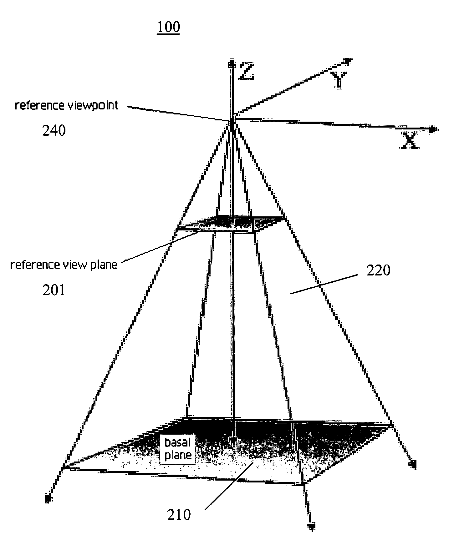
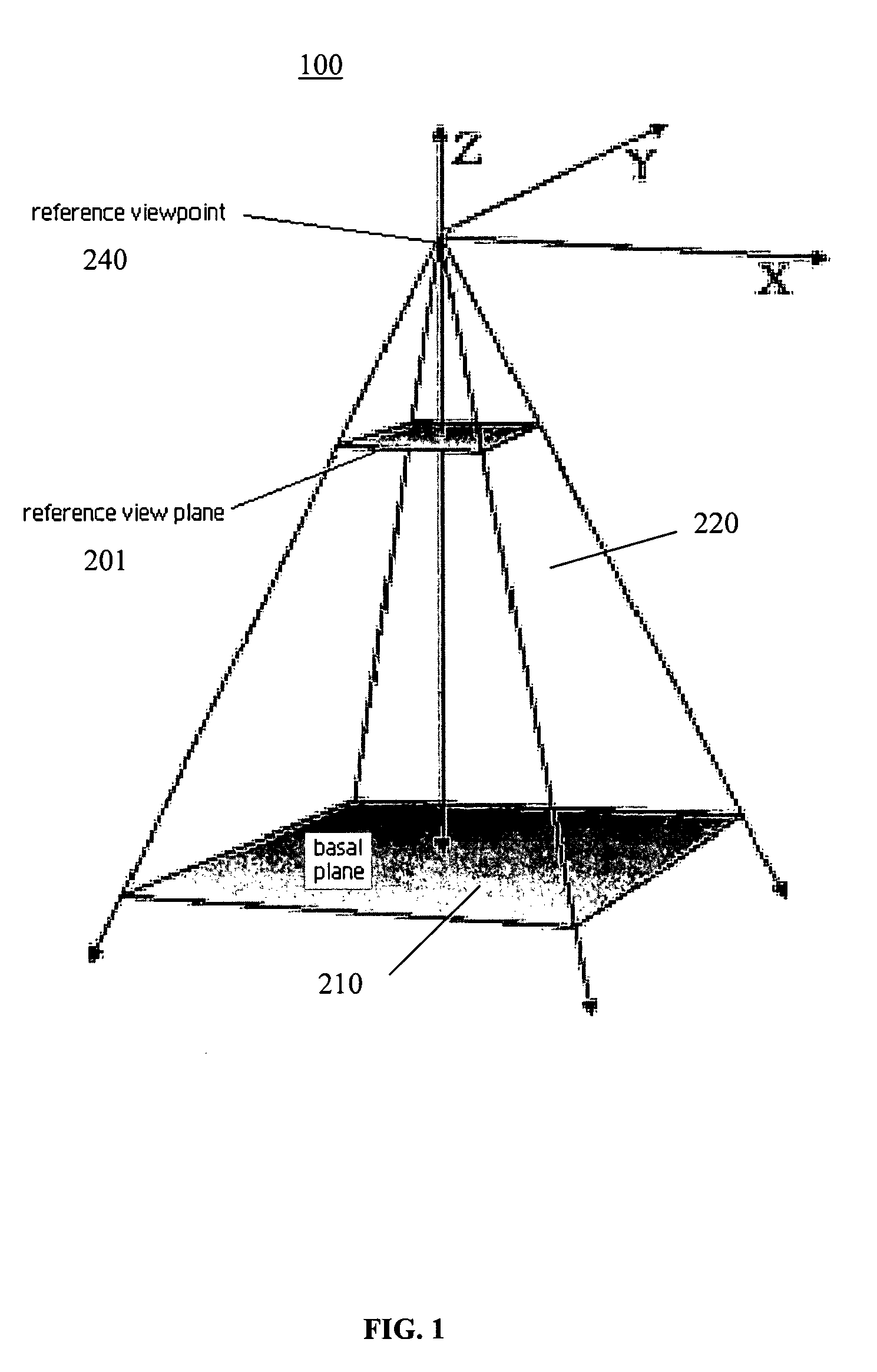
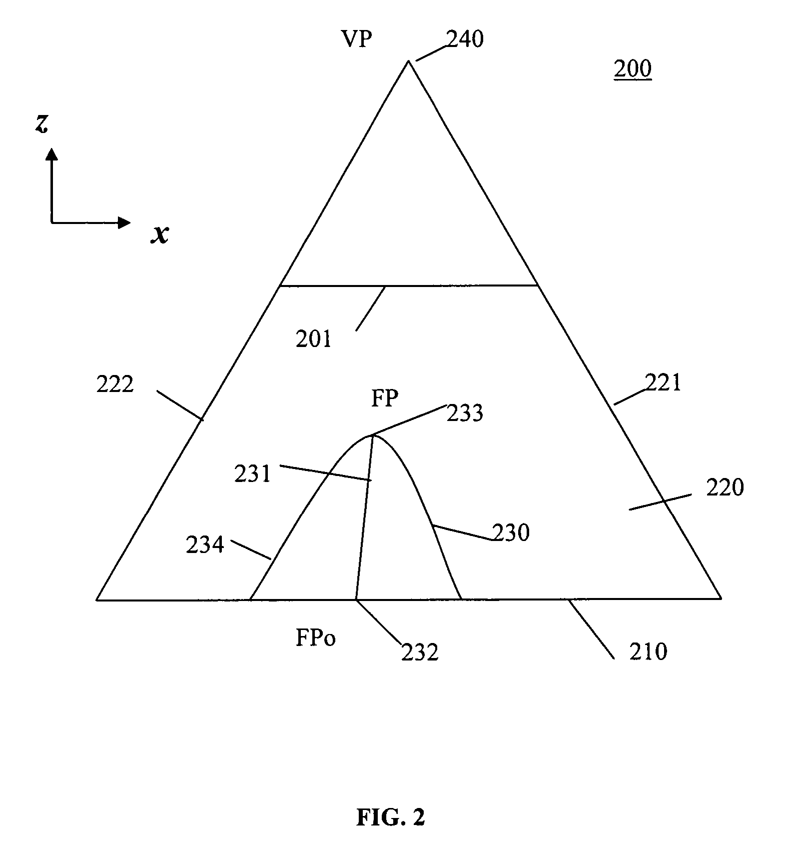
A method for generating a presentation of a region-of-interest in a terrain data representation for display on a display screen, comprising: translating each point of the representation within a lens bounds to a rotated plane being normal to a vector defined by a position for the region-of-interest with respect to a base plane for the representation and an apex above the base plane, the lens bounds defining a shoulder region at least partially surrounding a focal bounds defining a focal region in which the position is located, each point having a respective height above the base plane; displacing each translated point from the rotated plane by a function of the respective height and a magnification for the focal region, the magnification varying across the shoulder region in accordance with a drop-off function; rotating each displaced point toward a viewpoint for the region-of-interest to maintain visibility of each displaced point and each point of the data representation beyond the lens bounds when viewed from the viewpoint; and, adjusting each rotated point corresponding to the shoulder region to provide a smooth transition to the data representation beyond the lens bounds.

Description

[0001]This application claims priority from U.S. Provisional Patent Application No. 60 / 670,646, filed Apr. 13, 2005, and incorporated herein by reference.FIELD OF THE INVENTION[0002]The invention relates to the field of computer graphics processing, and more specifically, to a method and system for generating detail-in-context lens presentations for terrain or elevation data.BACKGROUND OF THE INVENTION[0003]Display screens are the primary visual display interface for computers. One problem with display screens is that they are limited in size, thus presenting a challenge to user interface design, particularly when large amounts of visual information are to be displayed. This problem is often referred to as the “screen real estate problem”. Known tools for addressing this problem include panning and zooming. While these tools are suitable for a large number of display applications, they become less effective when sections of the visual information are spatially related, for example i...

Claims


Application Information

Patent Timeline
Patent Type & Authority Patents(United States)
IPC IPC(8): G06T15/10
CPCG06T17/05G06T3/0018G06T3/047
Inventor MONTAGNESE, CATHERINETIGGES, MARK H. A.
Owner ACCESSIFY LLC
Learn More