[0008]In various exemplary embodiments, the technology described herein provides water conservation devices, systems, and methods for use in a toilet system adapted to control the flow of water, and thereby conserve water, and allow a user to selectively control whether a full or partial flush is activated.
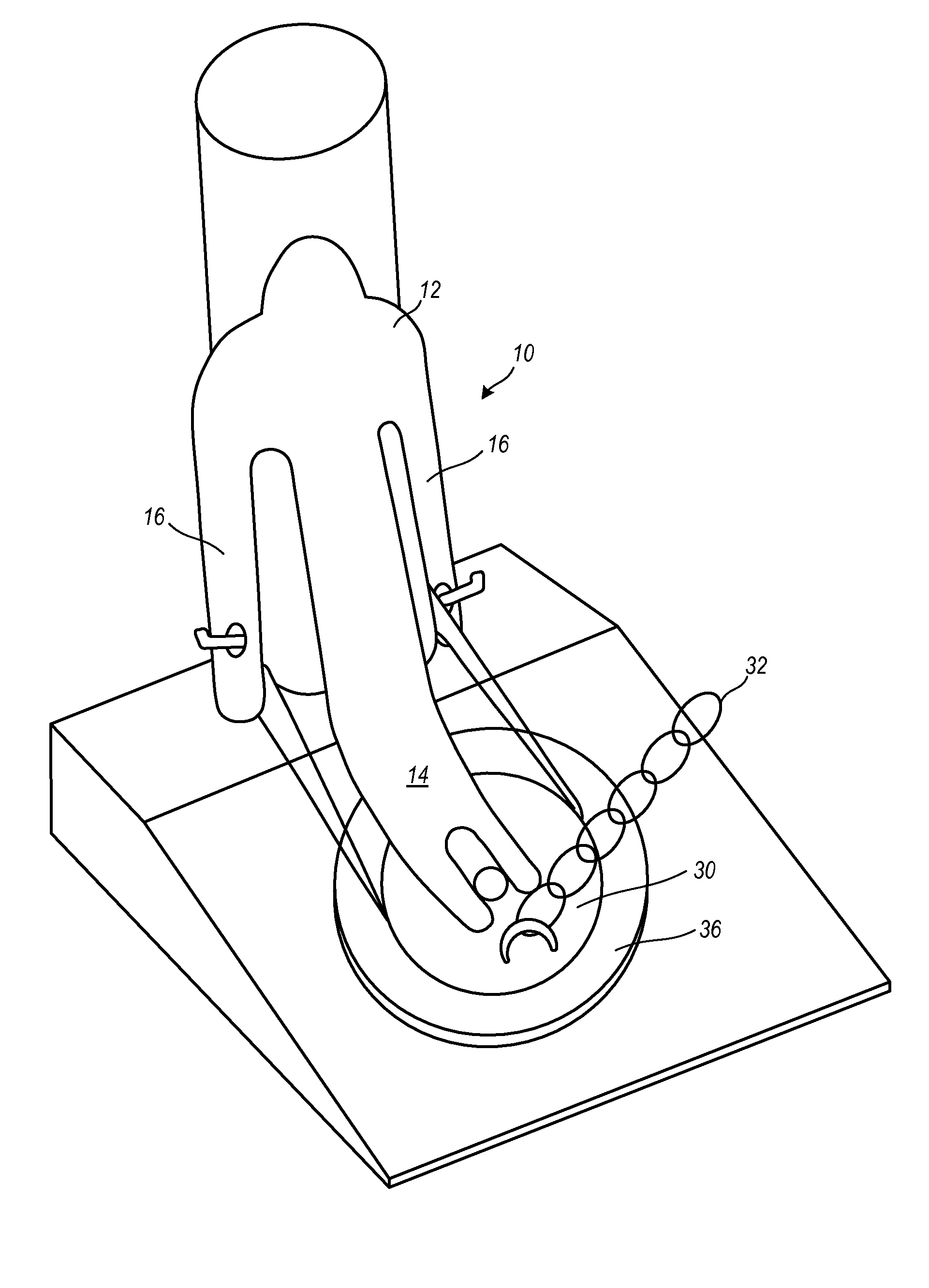
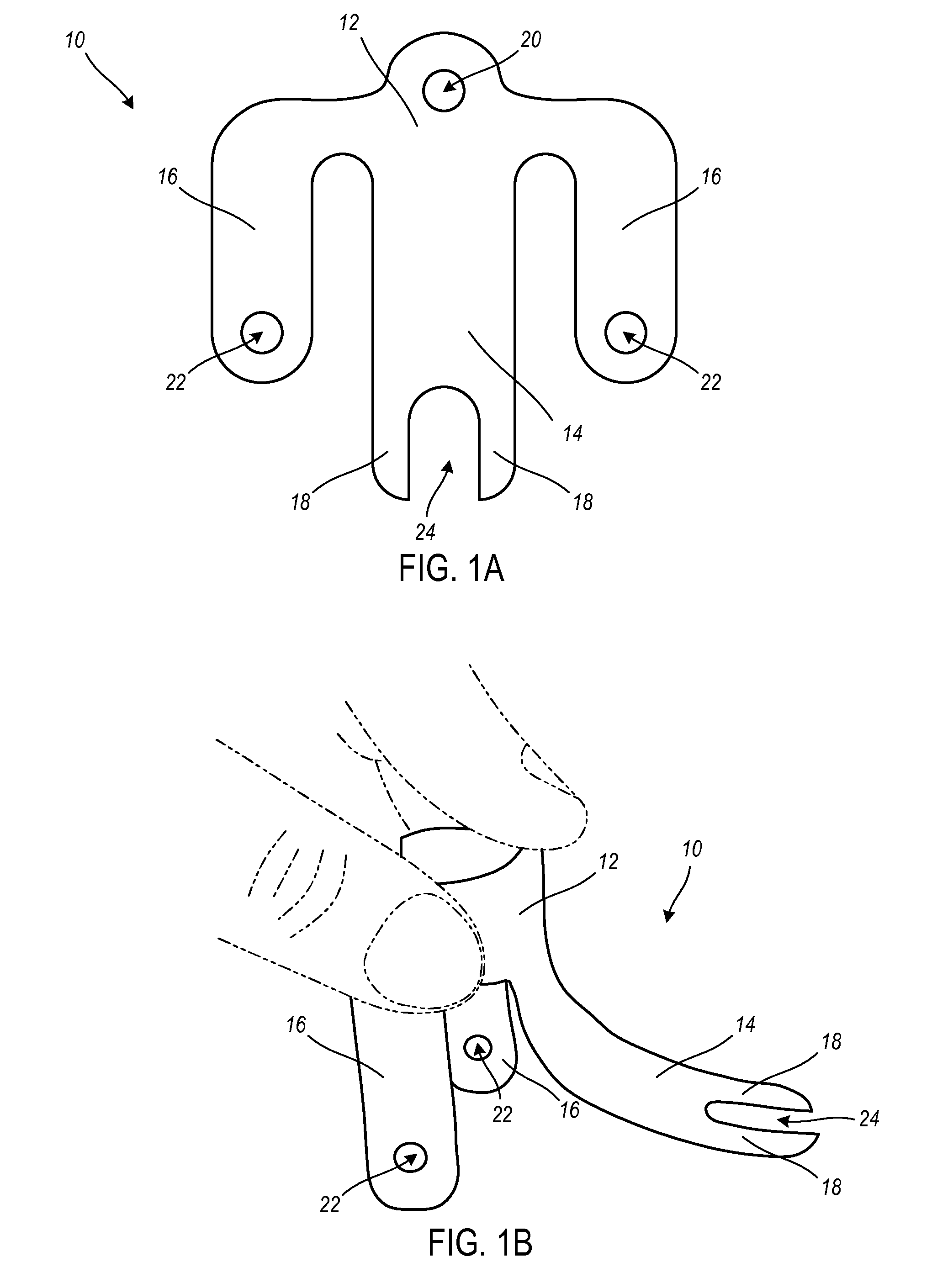
[0009]In one exemplary embodiment, the technology described herein provides a water conservation device for use within a toilet. The water conservation device includes: a connector having a base adapted for connectivity and placement adjacent to a traditional pole assembly and proximate to an opening valve, such as a flapper, within a tank of the toilet; and a flexible pressure arm integrally formed with the connector base and adapted to couple to the opening valve within the tank of the toilet and adapted to provide a pressure to the opening valve to lessen overall water utilized in each flush of the toilet and thereby conserve water. The water conservation device is adapted for either a total or partial flush of the toilet as selected by a user. The water conservation device also can include: a pair of arms integrally formed with the connector base, extending outwardly from each side, and adapted to couple to the traditional pole assembly within the tank of the toilet. The water conservation device further can include: a pair of feet integrally formed with the flexible pressure arm and each adapted to provide a pressure to the opening valve. The water conservation device also can include: a channel disposed between the pair of feet. The water conservation device can be a water resistant material. The water conservation device is thin and planar, adapted for flat transport, and adapted for foldout by a user and placement in the toilet tank coupled to the pole assembly and the opening valve. The water conservation device can include: an internal resistance element disposed within the connector base and adapted to provide greater rigidity and strength to the pressure arm. The internal resistance element can be a strip of spring steel.
[0010]In another exemplary embodiment, the technology described herein provides a toilet system. The toilet system includes: a tank; a bowl; a connector having a base adapted for connectivity and placement adjacent to a traditional pole assembly and proximate to an opening valve, such as a flapper, within the tank of the toilet; and a flexible pressure arm integrally formed with the connector base and adapted to couple to the opening valve within the tank of the toilet and adapted to provide a pressure to the opening valve to lessen overall water utilized in each flush of the toilet and thereby conserve water. The connector is adapted for either a total or partial flush of the toilet as selected by a user. The system also can include: a pair of arms integrally formed with the connector base, extending outwardly from each side, and adapted to couple to the traditional pole assembly within the tank of the toilet; a pair of feet integrally formed with the flexible pressure arm and each adapted to provide a pressure to the opening valve; and a channel disposed between the pair of feet. The water conservation device comprises a water resistant material.
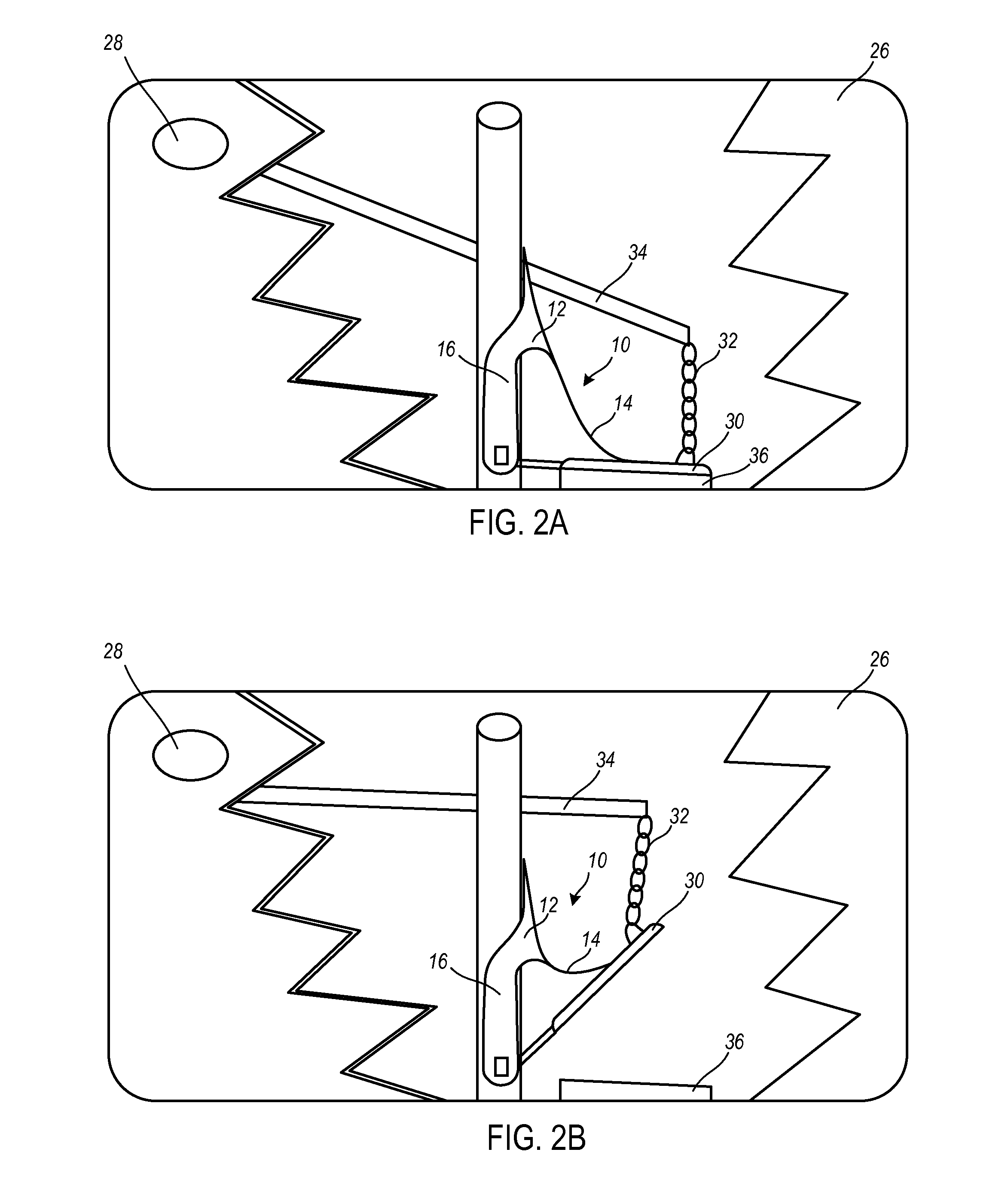
[0015]In yet another exemplary embodiment, the technology described herein provides a method for water conservation with a toilet. The method includes: utilizing a connector having a base adapted for connectivity and placement adjacent to a traditional pole assembly and proximate to an opening valve, such as a flapper, within a tank of the toilet and a flexible pressure arm integrally formed with the connector base and adapted to couple to the opening valve within the tank of the toilet and adapted to provide a pressure to the opening valve to lessen overall water utilized in each flush of the toilet and thereby conserve water; placing the connector adjacent to the traditional pole assembly and securing the connector to the traditional pole assembly; coupling the pressure arm to the opening valve within the tank of the toilet; and providing pressure from the pressure arm to the opening valve to restrict water flow and thereby conserve water with each flush of the toilet. The connector is adapted for either a total or partial flush of the toilet as selected by a user. The connector also can include a pair of arms integrally formed with the connector base, extending outwardly from each side, and adapted to couple to the traditional pole assembly within the tank of the toilet; a pair of feet integrally formed with the flexible pressure arm and each adapted to provide a pressure to the opening valve; and a channel disposed between the pair of feet. The method further can include: flushing the toilet with the pressure arm totally unrestricted and allowing the pressure arm to place a pressure to the opening valve, thereby limiting flush water from passage and conserving water; flushing the toilet with the pressure arm totally restricted from providing a pressure to the opening valve, thereby allowing a complete, normal flush, and in which no water is conserved; or flushing the toilet with the pressure arm partially restricted, based upon a specific flush need, providing a partially restricted pressure to the opening valve, and in which some water is conserved.
[0016]Advantageously, the water conservation device provides an easy to manufacture device that is preferably made of a single part. The single part is thin and planar, such that it can be mailed, transported, or the like and folded outwardly for installation in a toilet system. The device can be made of an inexpensive, water resistant material such as plastic. Also advantageously, the water conservation device is easy to install and requires minimal alteration to an existing toilet system. Further advantageously, the water conservation device can be coupled with use of electronic and / or mechanical system add-ons to further control and / or select the flush options of the toilet.
