Bifurcated stem foam pump

a foam pump and bifurcated stem technology, applied in the field of foam pumps, can solve the problems of increasing the cost of disposable cartridges and the cost of foam generating pumps

Active Publication Date: 2013-08-06
GOJO IND INC
View PDF28 Cites 18 Cited by
  • Summary
  • Abstract
  • Description
  • Claims
  • Application Information

AI Technical Summary

Problems solved by technology

However, foam generating pumps are more expensive than liquid dispensing pumps, necessarily increasing the cost of disposable cartridges that include the pump with each cartridge.

Method used


Image

  • Bifurcated stem foam pump
  • Bifurcated stem foam pump
  • Bifurcated stem foam pump

Examples


Embodiment Construction

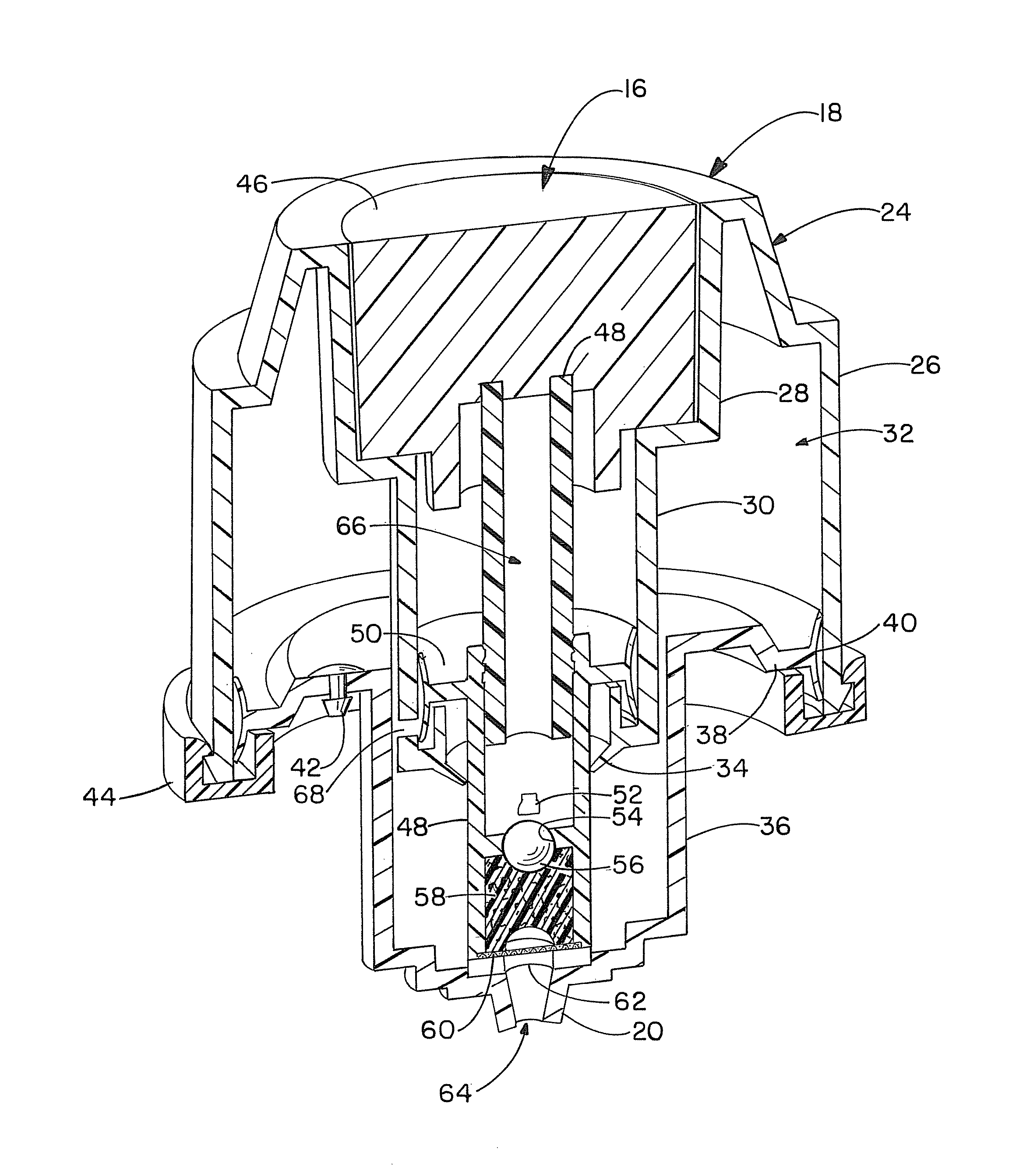
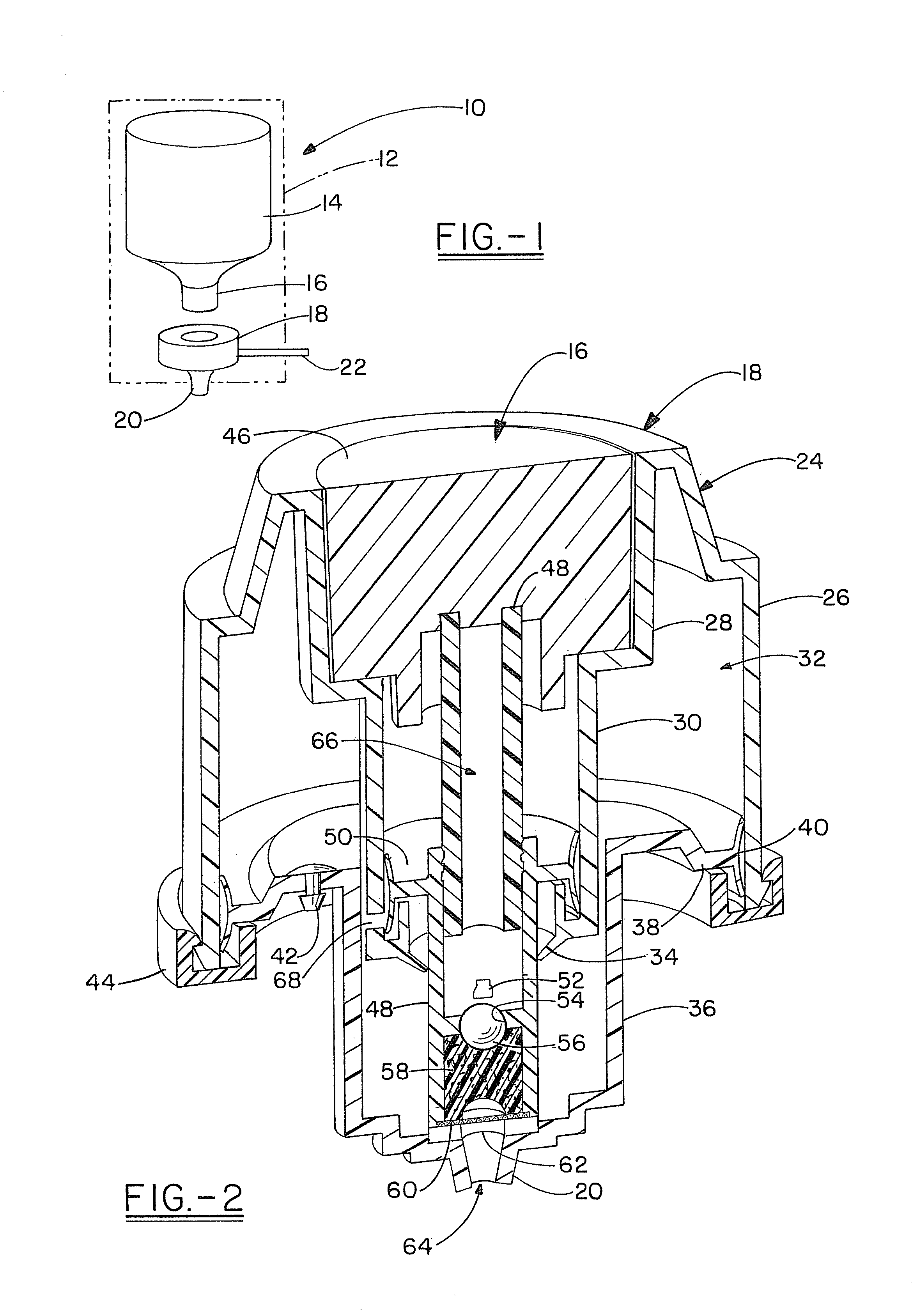
[0016]Referring now to the drawings and more particularly FIG. 1, it can be seen that a foam solution dispenser employing the bifurcated foam pump assembly of the invention is designated generally by the numeral 10. It will be appreciated that the foam solution dispenser may be of any of various types, adapted for dispensing soap, lotion, sanitizers, cleaners or the like in the form of a foam. The dispenser 10 includes a housing 12, typically of molded plastic or the like. The housing 12 defines a cavity which is adapted to receive a bottle or cartridge 14 of liquid of the particular type required for generating the desired foam. The bottle or cartridge 14 is nestingly received by the housing 10 and, may be received and contained by supporting brackets, collars and the like within the housing 12.

[0017]A liquid pump 16 is connected to and provided as a portion of the disposable refill cartridge or bottle 14. In contradistinction, an air compressor unit 18 is provided as part and parc...


PUM


Abstract

Foam dispensers having a housing and an air compressor connected to the housing are disclosed herein. The air compressor releasably mates with a refill unit. The refill includes a container and liquid pump housing. The liquid pump housing includes: a liquid reservoir; an inlet valve; an outlet valve; an air inlet opening through the liquid pump housing; a foaming screen; and a foam dispensing nozzle secured to the liquid pump housing. The liquid pump housing is configured to releasably mate with an air compressor that is not part of the refill unit but is secured to a foam pump dispenser housing, and the refill unit is configured to be removed from the foam dispenser without removing the air compressor from the foam dispenser.

Description

RELATED APPLICATIONS[0001]This application is a continuation-in-part of U.S. patent application Ser. No. 12 / 069,214, titled Bifurcated Stem Foam Pump, which was filed on Feb. 8, 2008 and will issue as U.S. Pat. No. 8,047,403 on Nov. 2, 2011. This application is also a continuation-in-part of U.S. patent application Ser. No. 12 / 069,321, titled Bifurcated Foam Pump Assembly, which was filed on Feb. 8, 2008. This application is a continuation-in-part of U.S. patent application Ser. No. 12 / 069,320, titled Bifurcated Stem Foam Pump, which was also filed on Feb. 8, 2008 and will issue as U.S. Pat. No. 8,047,404 on Nov. 2, 2011. This application claims priority to and the benefits of these three applications which are incorporated herein by reference.TECHNICAL FIELD[0002]Embodiments of the invention herein reside in the art of liquid dispensing mechanisms and, more particularly, to those mechanisms that are particularly adapted for dispensing a liquid in the form of a foam. Specifically, t...

Claims


Application Information

Patent Timeline
Patent Type & Authority Patents(United States)
IPC IPC(8): B67D7/76
CPCA47K5/14B05B7/2491B05B11/3074B05B11/3077B05B11/3087B05B11/0064B05B7/0037B05B7/0475B05B11/1077B05B11/1087B05B11/1074
Inventor QUINLAN, ROBERT L.ROSENKRANZ, MARK E.REYNOLDS, AARON R.
Owner GOJO IND INC
Why Eureka
Try Eureka