Head chip for ink jet type image forming apparatus

a technology of ink jet and image forming apparatus, which is applied in the direction of printing, other printing apparatus, etc., can solve the problems of critical head chip temperature, increased energy accumulated in the head chip, and increased temperature of the head chip, so as to prevent overheating of the ink ejection parts

Inactive Publication Date: 2013-08-06
HEWLETT PACKARD DEV CO LP
View PDF29 Cites 2 Cited by
  • Summary
  • Abstract
  • Description
  • Claims
  • Application Information

AI Technical Summary

Benefits of technology

[0009]The present general inventive concept provides a head chip for an ink jet type image forming apparatus with an improved cooling structure.
[0026]In accordance with another aspect of the present general inventive concept, there is provided a head chip for an ink jet type image forming apparatus including: a plurality of ink ejection parts to eject ink through nozzles by heating the ink; and a cooling channel to forcibly circulate a refrigerant around the ink ejection parts so as to prevent overheating of the ink ejection parts.

Problems solved by technology

Accordingly, a problem of adequately maintaining a temperature of the head chip becomes critical.
If a distance between the nozzles and a firing pulse applied to the heaters for ink ejection are gradually increased, energy accumulated in the head chip is increased, which causes temperature rise of the head chip.
As a result, properties of the ink may be changed, and printing quality may be deteriorated.
However, dissipating heat through a head chip is inefficient, and attaching an additional cooling member to a head chip reduces productivity and space efficiency.

Method used


Image

  • Head chip for ink jet type image forming apparatus
  • Head chip for ink jet type image forming apparatus
  • Head chip for ink jet type image forming apparatus

Examples


Embodiment Construction

[0050]Reference will now be made in detail to the embodiments of the present general inventive concept, examples of which are illustrated in the accompanying drawings, wherein like reference numerals refer to the like elements throughout. The embodiments are described below to explain the present general inventive concept by referring to the figures.

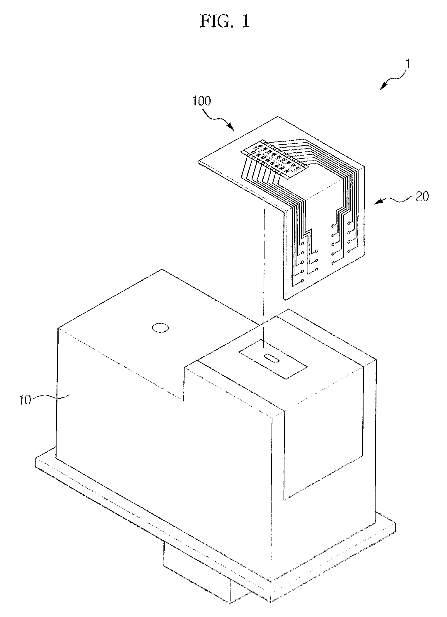
[0051]FIG. 1 is a perspective view illustrating a cartridge for an ink jet type image forming apparatus according to an embodiment of the present general inventive concept.

[0052]A cartridge 1 of this embodiment may include an ink storage unit 10 to store ink therein, a head chip 100 seated in the ink storage unit 10 to eject ink, and a printed circuit board 20 having circuits and signal lines to drive the head chip 100.

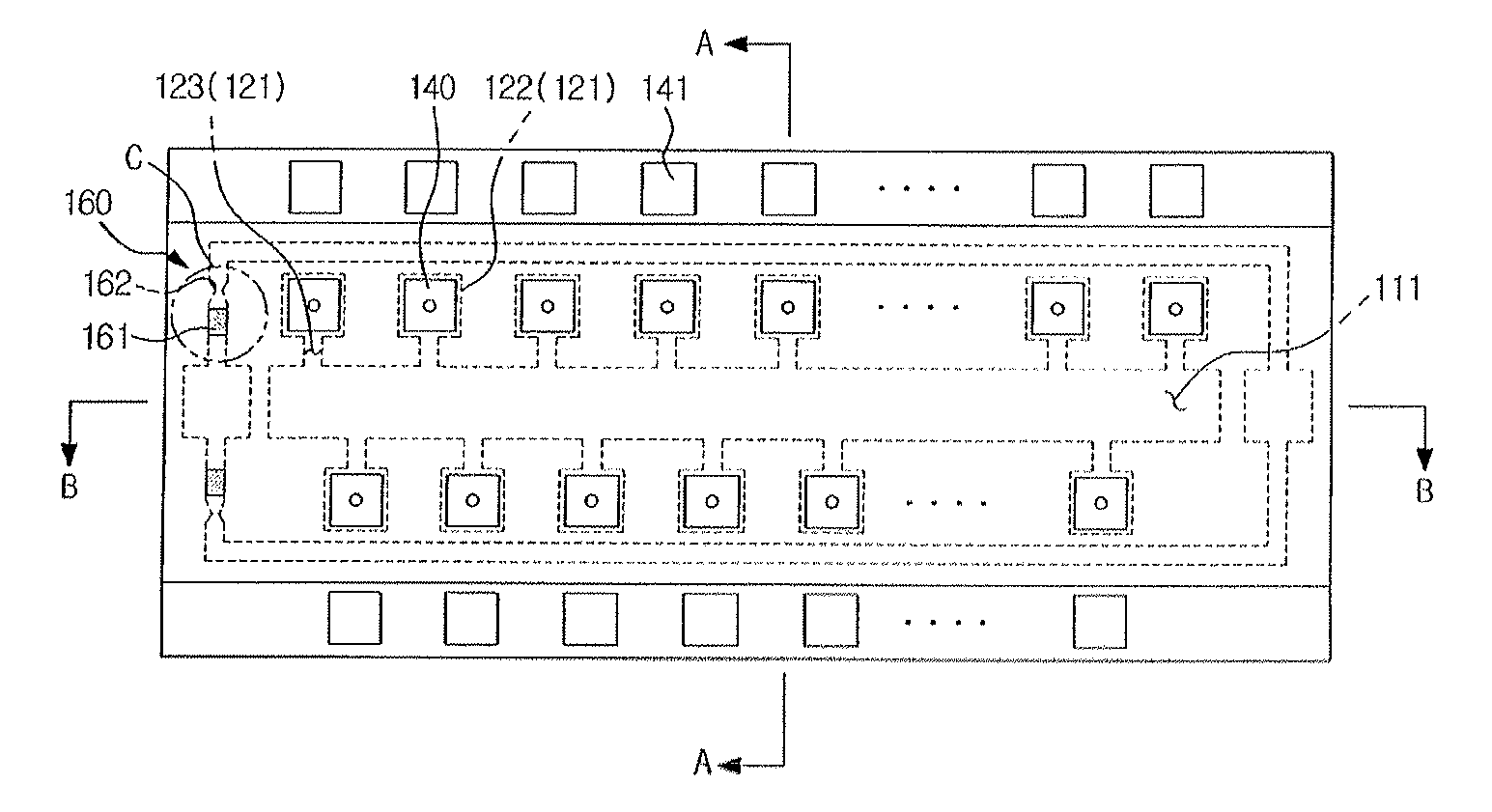
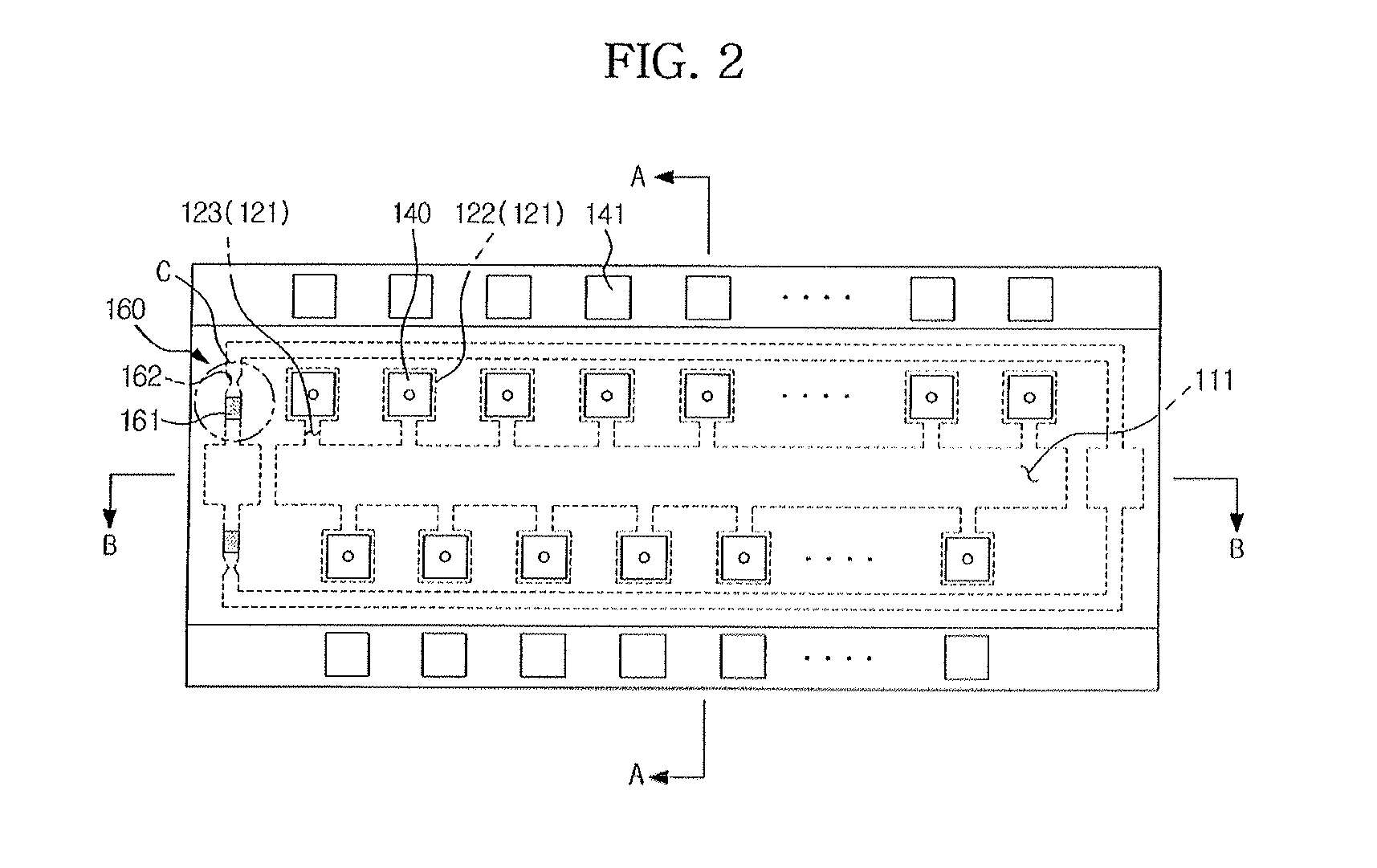
[0053]FIG. 2 is a plan view illustrating a constitution of the head chip according to an embodiment of the present general inventive concept, FIG. 3 is a sectional view taken along line A-A of FIG. 2, and FIG. 4 is a secti...


PUM


Abstract

A head chip for an ink jet type image forming apparatus with an improved cooling structure is disclosed. The head chip includes a plurality of nozzles to eject ink, a plurality of heaters for ink ejection to apply heat to ink so that the ink is ejected through the plurality of nozzles, and a cooling channel to circulate a refrigerant around the plurality of heaters for ink ejection.

Description

CROSS-REFERENCE TO RELATED APPLICATIONS[0001]This application claims the benefit of Korean Patent Application No. 2008-0069466, filed on Jul. 17, 2008 in the Korean Intellectual Property Office, the disclosure of which is incorporated herein by reference in its entirety.BACKGROUND OF THE INVENTION[0002]1. Field of the Invention[0003]The present general inventive concept relates to a head chip for an ink jet type image forming apparatus, and, more particularly, to a head chip with an improved cooling structure.[0004]2. Description of the Related Art[0005]An ink jet type image forming apparatus refers to an apparatus to form an image by ejecting fine ink droplets onto a desired position on a printing medium. Such an ink jet type image forming apparatus is generally classified as an electro-thermal type and a piezoelectric type. The electro-thermal type ink jet image forming apparatus generates bubbles in the ink using a heat source provided at a head chip, and ejects ink droplets thro...

Claims


Application Information

Patent Timeline
Patent Type & Authority Patents(United States)
IPC IPC(8): B41J29/377B41J29/38B41J2/335B41J2/34B41J2/165B41J2/015
CPCB41J2/1408B41J2/1753B41J2/17553B41J2/1404B41J2/14056B41J2/14129B41J2/14137B41J2/14145
Inventor SUH, JUN WOO
Owner HEWLETT PACKARD DEV CO LP
Why Eureka
Try Eureka