Fuel cell stack having improved cooling structure
a fuel cell and stack technology, applied in the field of stacks with improved cooling structures and fuel cell systems, can solve the problems of stack performance degradation and stack cooling efficiency drop, and achieve the effect of improving stack cooling efficiency and stack performan
- Summary
- Abstract
- Description
- Claims
- Application Information
AI Technical Summary
Benefits of technology
Problems solved by technology
Method used
Image
Examples
first embodiment
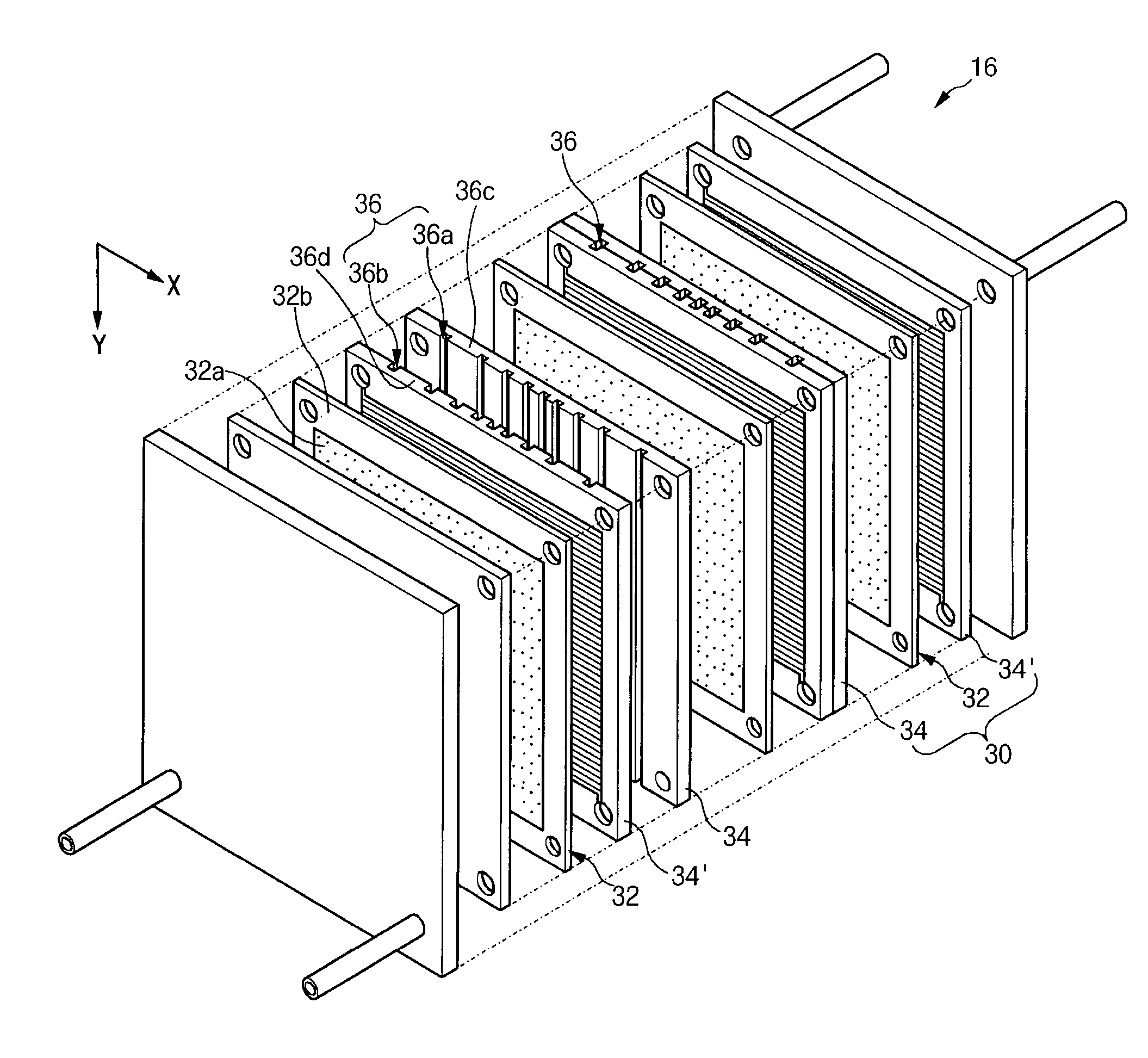
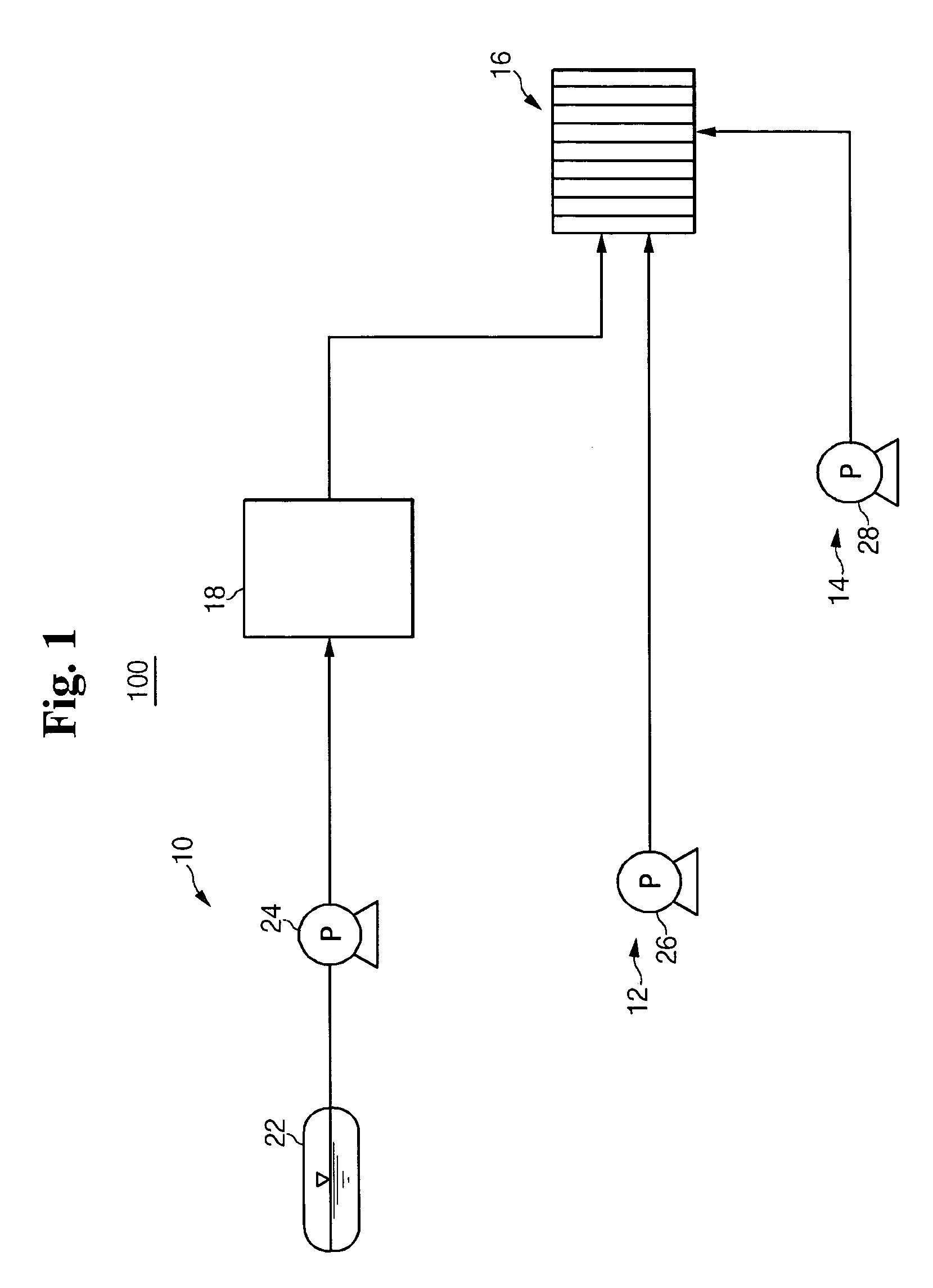
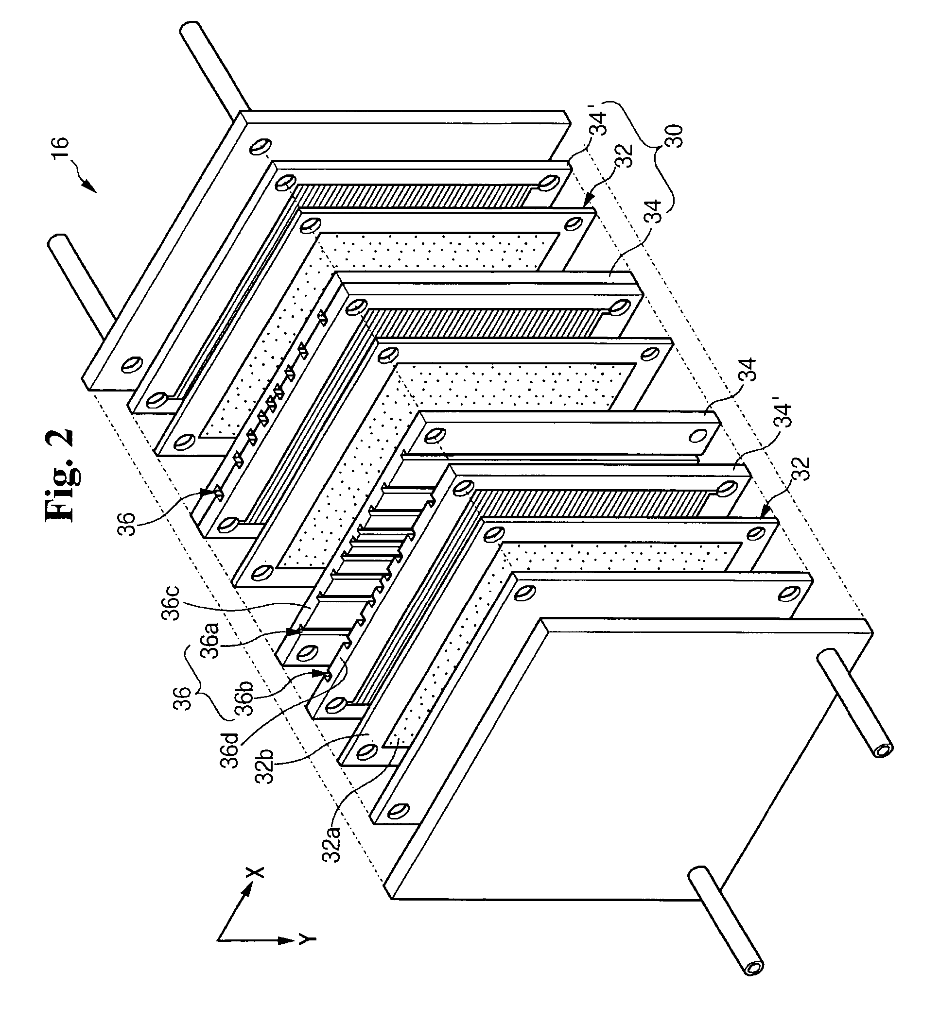
[0030]FIG. 2 is an exploded perspective view illustrating a stack 16 according to the present invention. The stack 16 in the fuel cell system 10 includes electricity generators 30 as a minimum unit generating electric energy, in which separators 34, 34′ are placed in close contact with both surfaces of a MEA 32. The separators are also referred to as “bipolar plates” in the art. The stack 16 is constructed by sequentially stacking a plurality of the electricity generators 30.
[0031]An anode is formed on one side of the MEA 12, and a cathode is formed on the other side of the MEA 12. The MEA 12 has an electrolyte membrane between the anode and the cathode. The anode receives the reformed gas through the separator 34. The anode is constructed with a catalyst layer decomposing the reformed gas into electrons and hydrogen ions and a gas diffusion layer promoting movement of the electrons and the reformed gas. The cathode receives the air through the separator 34′. The cathode is construc...
second modified embodiment
[0056]In the second modified embodiment, the shape of the cooling channels 36B changes, allowing the distribution density of the cooling channels 36B to change depending on the region of the separators 34B. This structure further improves the cooling efficiency of the stack 16.
[0057]FIG. 6 is an exploded perspective view illustrating a stack 16′ according to a second embodiment of the present invention. In comparison to the stack 16 of the first embodiment shown in FIG. 2, the stack 16′ shown in FIG. 4 further includes cooling plates 38. The cooling plates 38 are interposed between adjacent electricity generators 30′ and more specifically between the separators 37 and 37′ of two adjacent electricity generators 30′. The cooling plates 38 function as heat release plates for releasing thermal energy transferred from the separators 37 and 37′ during the operation of the electricity generators 30′.
[0058]Because the cooling plates 38 cool the entire MEA 32′, cooling efficiency is improved...
second embodiment
[0059]A plurality of cooling channels 36′ are formed within the cooling plates 38 and extend along one of the edges of the cooling plates 38, for example, the X direction in FIG. 6. The cooling channels 36′ of the second embodiment receive the coolant from the coolant supply unit 14 shown in FIG. 1 and cool the stack 16′. These cooling channels 36′ operate similarly to the cooling channels 36, 36A, 36B that were previously discussed. Therefore, detailed description on the construction and operations of these channels is omitted.
PUM
| Property | Measurement | Unit |
|---|---|---|
| thickness | aaaaa | aaaaa |
| electric energy | aaaaa | aaaaa |
| distribution density | aaaaa | aaaaa |
Abstract
Description
Claims
Application Information
 - R&D
- Intellectual Property
- Life Sciences
- Materials
- Tech Scout
- Unparalleled Data Quality
- Higher Quality Content
- 60% Fewer Hallucinations
Browse by: Latest US Patents, China's latest patents, Technical Efficacy Thesaurus, Application Domain, Technology Topic, Popular Technical Reports.
© 2025 PatSnap. All rights reserved.Legal|Privacy policy|Modern Slavery Act Transparency Statement|Sitemap|About US| Contact US: help@patsnap.com


