
Indoor unit for air conditioner

a technology for indoor units and air conditioners, which is applied in the direction of domestic cooling devices, lighting and heating devices, heating types, etc., can solve the problems of difficult accurate measurement of room temperature, inability to accurately detect room temperature by temperature sensors, and difficulty in performing air duct cleaning, etc., to achieve convenient operation, reduce manufacturing costs, and improve air circulation

Active Publication Date: 2013-08-13
LG ELECTRONICS INC
View PDF19 Cites 7 Cited by
  • Summary
  • Abstract
  • Description
  • Claims
  • Application Information

AI Technical Summary

Benefits of technology

[0018]According to the present invention, since the connecting frame is detachably mounted on the lower end of the front frame, it is convenient to perform the maintenance service for the internal components such as the air discharge vane.
[0019]In addition, since the connecting frame is connected to both of the front frame and the main chassis, the front frame can be more securely coupled to the main chassis.
[0020]Furthermore, since the air discharge panel and air discharge vane are provided on the lower end of the front frame, the discharge direction of the air can be controlled and thus the air circulation can be more effectively realized.
[0021]In addition, since the air sealing member is provided between the front frame and the main chassis, the air leakage through the gap between the front frame and the main chassis can be prevented.
[0022]Since the components can be commonly used by the air sealing member, the manufacturing cost can be reduced. That is, since the panel driving unit for driving the air discharge panel and front-upper panel is installed on the front frame, the horizontal length of the front frame increases. In this case, by providing the air sealing member, a conventional main chassis can be used. Therefore, there is no need to prepare a new main chassis for the front frame having the increased length. Therefore, the manufacturing cost can be remarkably reduced.
[0023]In addition, since the temperature detecting sensor is detachably mounted on the air sealing member, the room temperature can be accurately detected.

Problems solved by technology

In addition, during the discharge of the cooled air to the room, the cooled air may leak through a coupling portion between the main chassis and the front panel.
Furthermore, since a temperature sensor is installed on a front surface of the heat exchanger, it is difficult to accurately measure the room temperature.
That is, the temperature detected by the temperature sensor is closer to the surface temperature of the heat-exchanger and thus the room temperature cannot be accurately detected by the temperature sensor.

Method used


Image

  • Indoor unit for air conditioner
  • Indoor unit for air conditioner
  • Indoor unit for air conditioner

Examples


Embodiment Construction

[0044]While the present invention has been particularly shown and described with reference to exemplary embodiments thereof, it will be understood by those of ordinary skill in the art that various changes in form and details may be made therein without departing from the spirit and scope of the present invention as defined by the following claims.

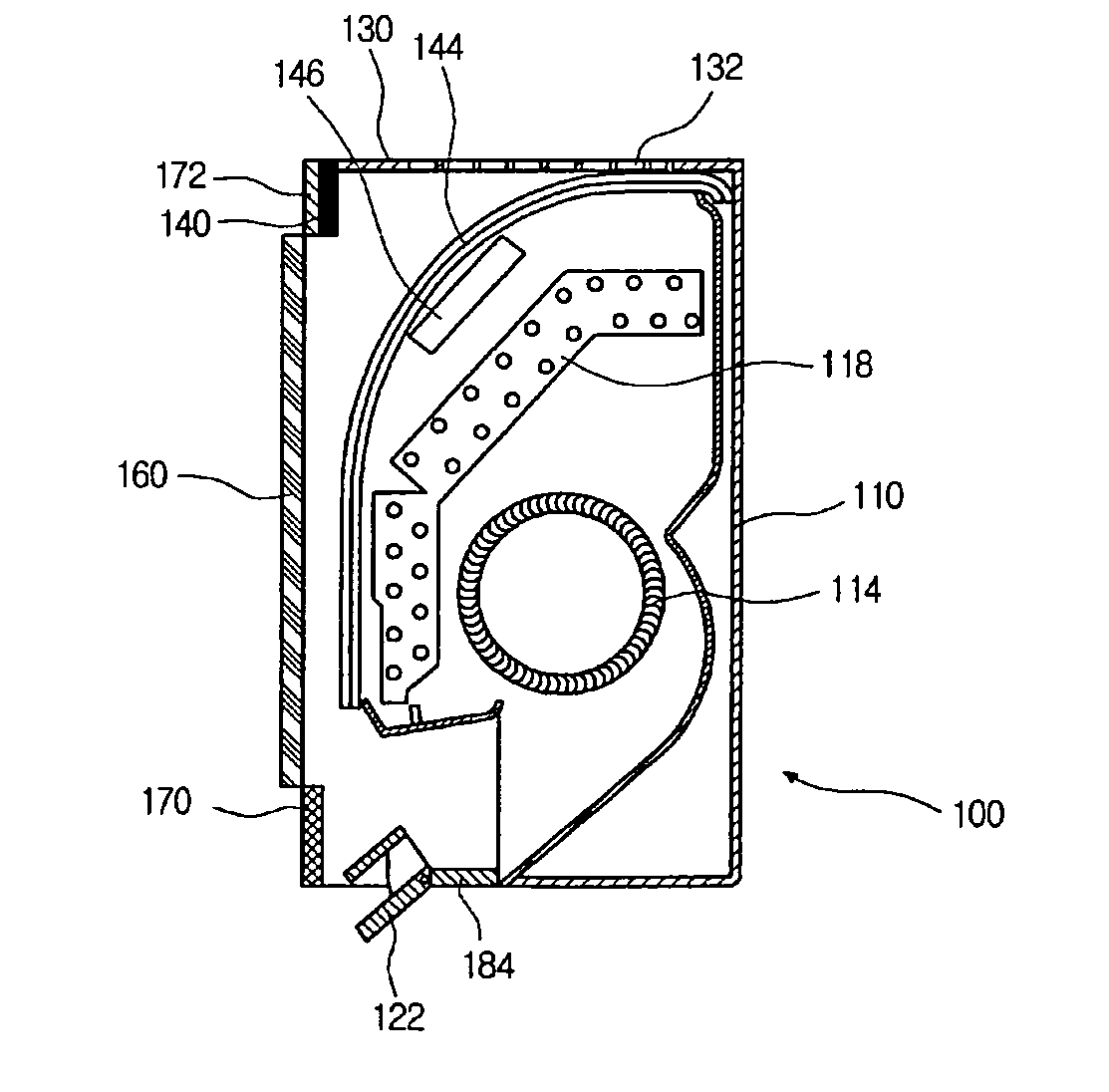
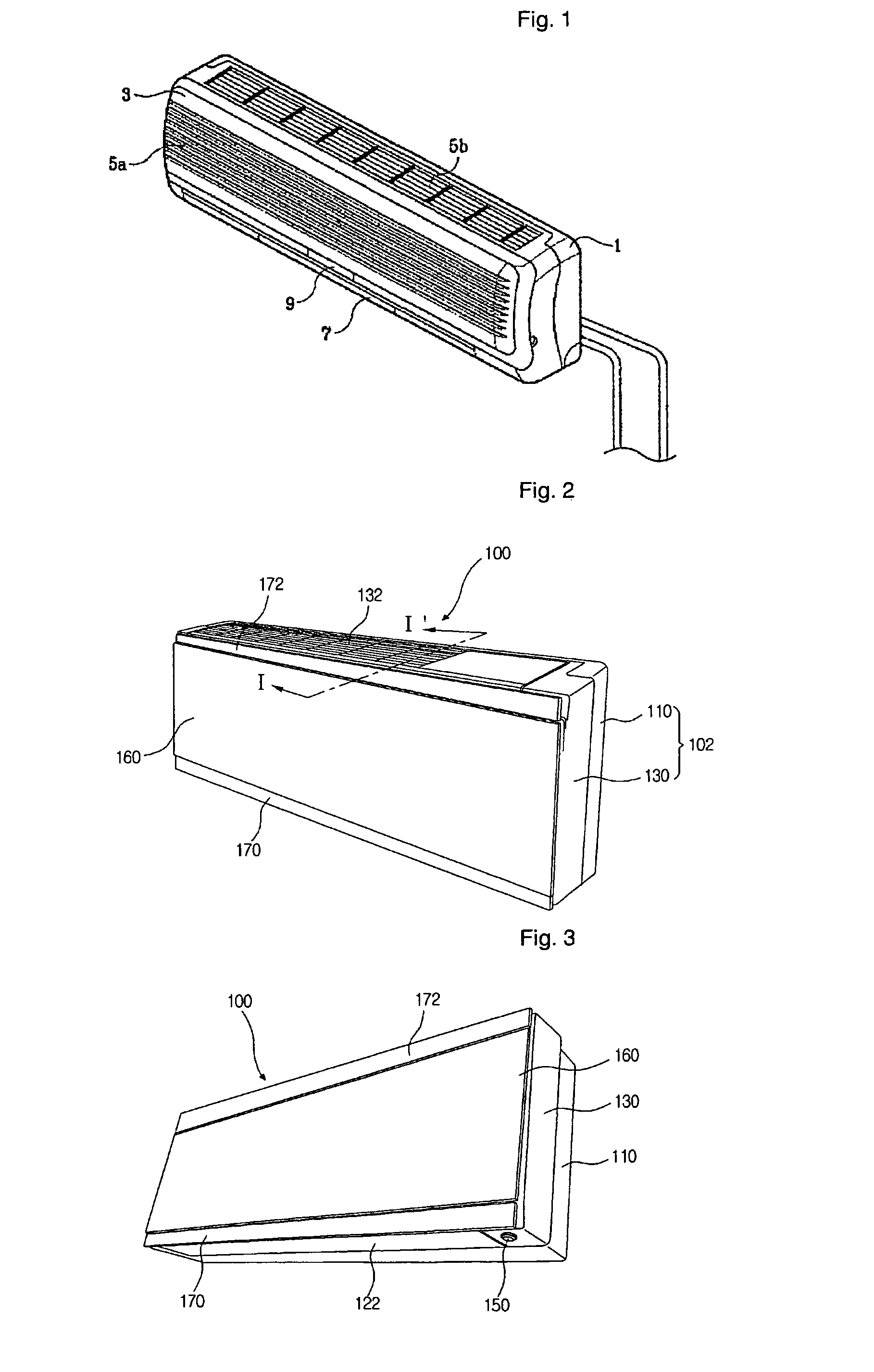
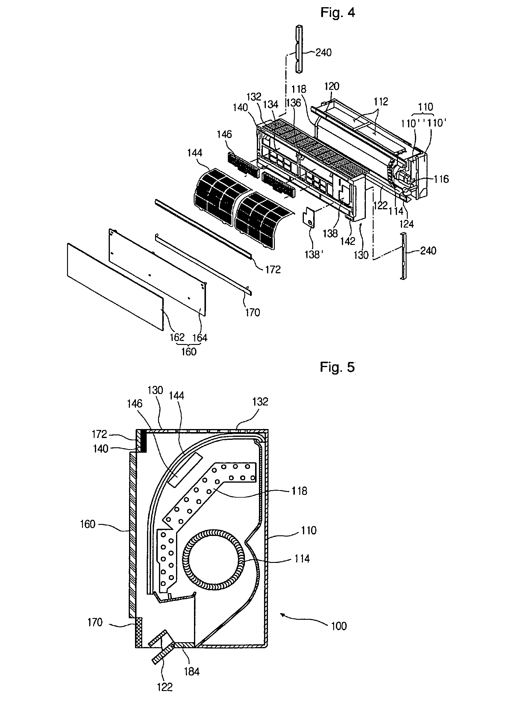
[0045]FIGS. 2 and 3 show an indoor unit for an air conditioner according to an embodiment of the present invention.

[0046]Referring to FIGS. 2 and 3, an indoor unit 100 includes a casing 102, a front panel 160 coupled to a front portion of the casing 102, an air discharge panel 170 slidably coupled to a lower end of the front panel 160, a front-upper panel 172 slidably coupled to an upper end of the front panel 160, and an air discharge vane 122 slidably coupled to a lower end of the casing 102.

[0047]The casing 102 includes a main chassis 110 and a front frame 130 coupled to a front portion of the main chassis 110 and a front frame 130 coup...


PUM


Abstract

An indoor unit for an air conditioner includes a front frame, a main chassis coupled on a rear portion of the front frame, an air discharge vane provided on a lower end of the front frame to control a discharge direction of cooled air, and an connecting frame provided in rear of the air discharge vane to allow an assembling or maintenance of the air discharge vane to be easily performed.

Description

[0001]This application is a national stage entry of PCT Patent Application No. PCT / KR2006 / 004754, filed Nov. 13, 2006, and claims the benefit of: Korean Patent Application No. 10-2006-0004226, filed Jan. 16, 2006; Korean Patent Application No. 10-2006-0004228, filed Jan. 16, 2006; and Korean Patent Application No. 10-2006-0004229, filed Jan. 16, 2006, which are all hereby incorporated herein by reference in their entireties.TECHNICAL FIELD[0002]The present invention relates to an air conditioner for an indoor unit.BACKGROUND ART[0003]Generally, an air conditioner is a system that is used to control the temperature, relative humidity or purity of air, ad to circulate cooled air in an enclosed space such as a room. The air conditioner is classified into an integration type where all of components are provided in a unit and a separation type having indoor and outdoor units separated from each other.[0004]FIG. 1 shows a perspective view of an indoor unit of a conventional air conditione...

Claims


Application Information

Patent Timeline
Patent Type & Authority Patents(United States)
IPC IPC(8): F25D17/04F24F1/0057F24F1/0063F24F1/0073F24F1/0076
CPCF24F1/0007F24F1/0011F24F13/20F24F11/0012F24F2001/0048F24F11/30F24F2110/10F24F1/0057F24F1/0073F24F1/0076F24F1/0063F24F11/52F24F11/79F24F11/56
Inventor SON, YANG-MOJU, JEONG-WEON
Owner LG ELECTRONICS INC
Learn More