Transfer ring which resists backdriving forces during a tire construction process

a technology of transfer rings and backdriving forces, which is applied in the field of transfer rings, can solve the problems of promoting damage to various components of the transfer rings, packaging tends to contract, etc., and achieves the effect of uniform grasping for

Active Publication Date: 2013-08-13
BPS ENG
View PDF10 Cites 0 Cited by
  • Summary
  • Abstract
  • Description
  • Claims
  • Application Information

AI Technical Summary

Benefits of technology

[0015]The improvement includes means for moving the shoes radially inwardly to a radial position about the outer circumference of a belt and tread package positioned within the transfer ring so that when in the radial position, the outer circumference of the belt and tread package is biased radially inwardly by the shoes so that in the event that the belt and tread package contracts in diameter following the movement of the shoes into the radial position, the shoes are moved radially inwardly of the belt and tread package to maintain a substantially uniform grasping force about the belt and tread package. In addition, there are provided means for preventing the shoes from moving radially outwardly of the radial position when a tire carcass is inflated within the interior of the belt and tread package grasped by the shoes to thereby prevent the diameter of the belt and tread package from enlarging beyond a desired diameter.

Problems solved by technology

However, in some instances, the size (e.g. the diameter) of the package tends to contract due, for example, to hoop stress which may be induced within the package when constructed, and unless compensated for, such a contraction of the package size could relieve some of the grasping pressure being applied to the package by the shoes so that the package is permitted to deform to a deleterious shape.
However, radially outwardly-directed forces which are exerted against the shoes during the inflation of the carcass can be so great that the shoes tend to be displaced radially outwardly from their original position of engagement with the outer circumference of the belt and tread package.
Such a radially outwardly-directed displacement, or shifting, of the shoes due to such outwardly-directed forces (referred to herein as backdriving forces) is a highly undesirable occurrence in that it promotes inaccuracies in the dimensions of the tire being constructed (i.e. permits the enlargement of the belt and tread package beyond a desired diameter) and can promote damage to various components of the transfer ring which oppose the backdriving forces.

Method used


Image

  • Transfer ring which resists backdriving forces during a tire construction process
  • Transfer ring which resists backdriving forces during a tire construction process
  • Transfer ring which resists backdriving forces during a tire construction process

Examples


Embodiment Construction

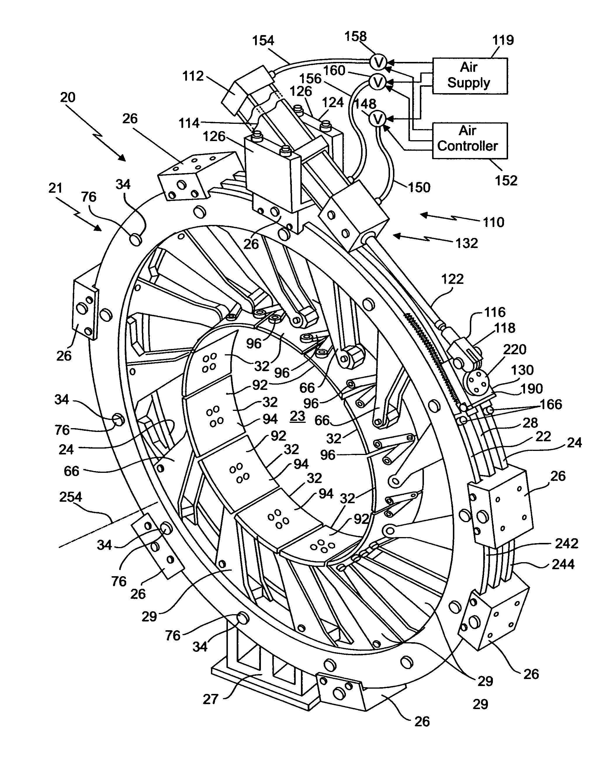
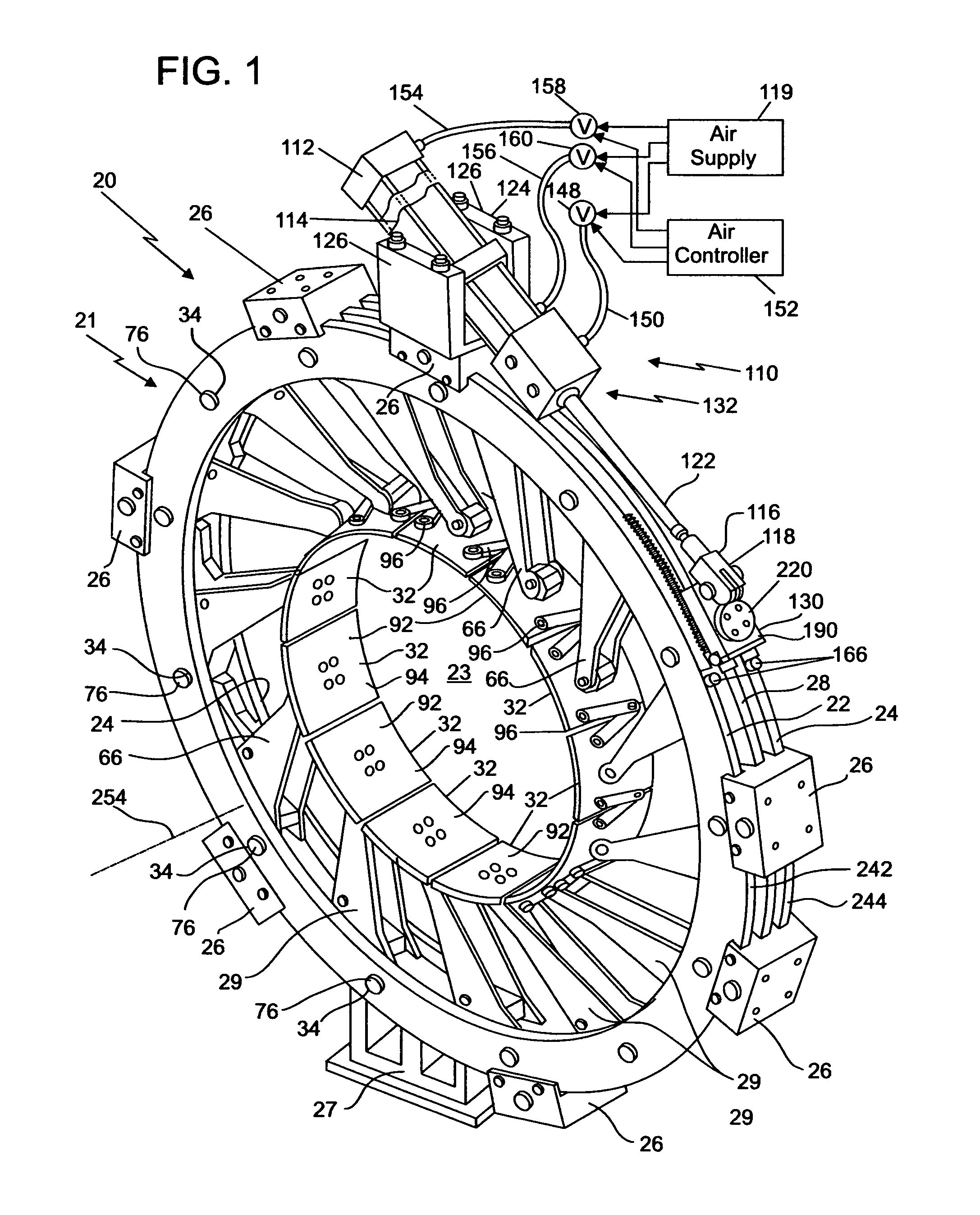
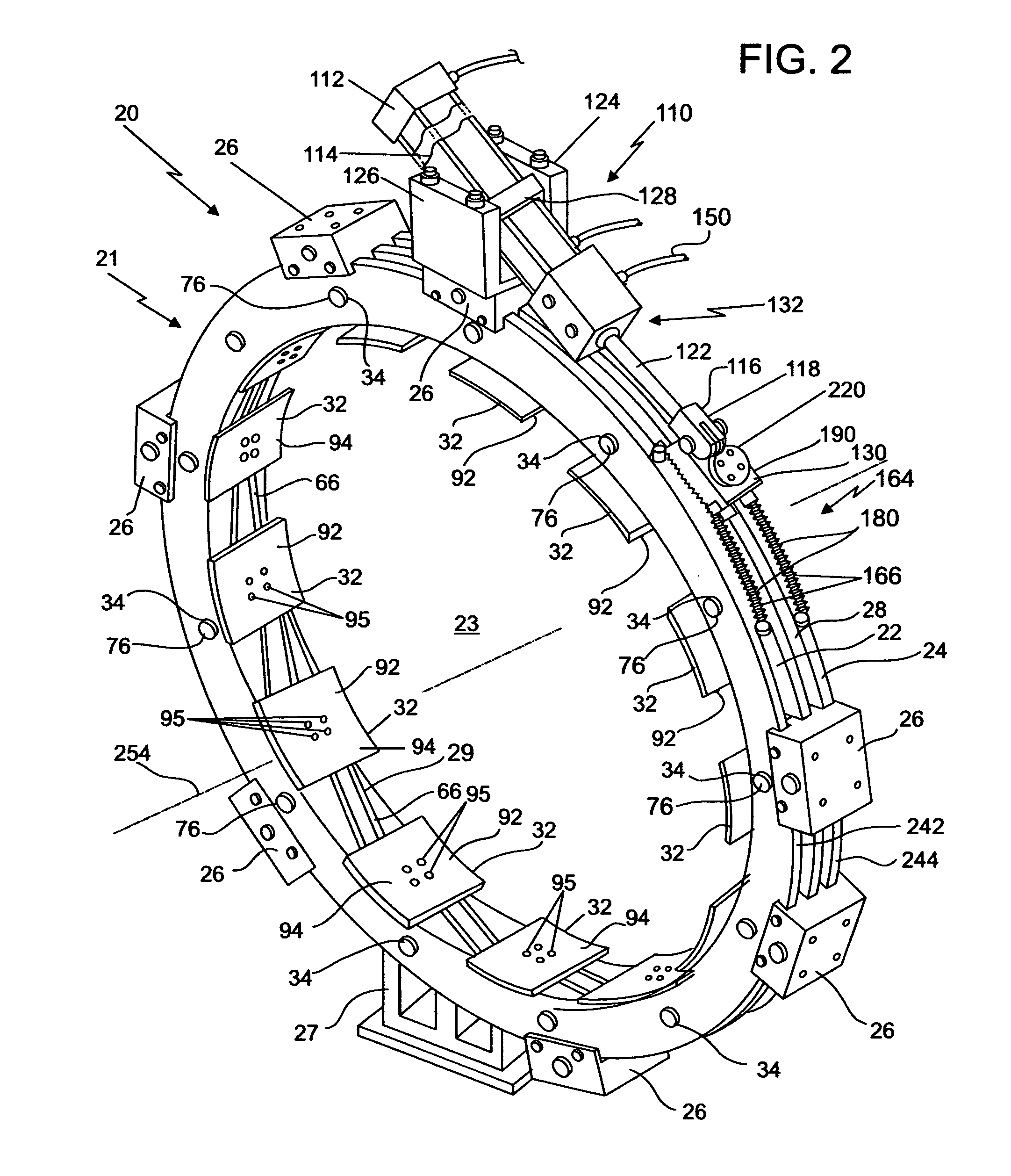
[0033]Turning now to the drawings in greater detail and considering first FIGS. 1 and 2, there is illustrated an embodiment, generally indicated 20, of a transfer ring which is used during the manufacture of vehicle tires and which embodies features of the present invention. More specifically, the transfer ring 20 is positionable about a belt and tread package (not shown) built upon a first stage tire-building drum, and a plurality of shoes are used to grasp the belt and tread package for transport to a position about a tire carcass which is supported about a second stage drum (e.g. a shaping drum). While the belt and tread package remains grasped by the shoes 32 of the transfer ring 20, the tire carcass is subsequently inflated in a manner which urges the outer surface of the tire carcass against the interior of the belt and tread package to form a tire precursor which is later placed in a mold for final formation of the tire and its tread. It is during the carcass-inflating proces...


PUM

PropertyMeasurementUnit
circumferenceaaaaaaaaaa
diameteraaaaaaaaaa
movementaaaaaaaaaa

Abstract

A transfer ring for supporting a belt and tread package about a tire carcass for inflation of the carcass within the package during a tire-making process includes a plurality of shoes which are movable inwardly and outwardly for purposes of grasping or releasing a package positioned between the shoes. Components are provided for moving the shoes inwardly to a radial position about a package; and at this radial position, the shoes apply to the package a biasing force for maintaining a substantial uniform pressure about the package if it were to contract in size after the shoes are moved to the radial position. A braking arrangement is provided which prevents the shoes from moving outwardly of the radial position when a tire carcass is thereafter inflated within the package to thereby limit the diameter of the package during the carcass-inflating process.

Description

BACKGROUND OF THE INVENTION[0001]This invention relates generally to the construction of vehicle tires and relates, more particularly, to a transfer ring used in a tire construction process.[0002]During the construction of a vehicle tire, a tire carcass is built upon a first stage tire-building drum and transferred to a second stage drum (e.g. a shaping drum) where it awaits a belt and tread package of the vehicle tire to be positioned thereon. The belt and tread package is constructed on a separate drum (i.e. a belt and tread drum) and transferred, by way of a transfer ring, to the second stage drum upon which the carcass has already been positioned. While positioned about a belt and tread drum, the belt and tread package is encircled and grasped by the transfer ring, and the belt and tread drum is collapsed so that the belt and tread package is supported by the transfer ring for subsequent transfer to the second stage drum.[0003]With the belt and tread package supported within the...

Claims


Application Information

Patent Timeline
Patent Type & Authority Patents(United States)
IPC IPC(8): B29D30/26
CPCB29D30/2607
Inventor BYERLEY, MARK S.
Owner BPS ENG
Why Eureka
Try Eureka