Floor structure for a motor vehicle

Inactive Publication Date: 2013-08-13
GM GLOBAL TECH OPERATIONS LLC
View PDF89 Cites 23 Cited by
  • Summary
  • Abstract
  • Description
  • Claims
  • Application Information

AI Technical Summary

Benefits of technology

[0015]According to another embodiment of the invention, great protection of a starter battery can be simply achieved if a starter battery of a combustion engine of the motor vehicle is arranged in the mounting. Because of this, the starter battery is protected from damage and thus leaking in the event of a crash. In addition it can be largely prevented by this that terminals of the starter battery come in contact with metal

Problems solved by technology

Because of this, the components require a lot of space which particularly in the rear region of the floor structure limits the possibility of arranging a spare wheel or a preferably large

Method used


Image

  • Floor structure for a motor vehicle
  • Floor structure for a motor vehicle
  • Floor structure for a motor vehicle

Examples


Example

[0024]The following detailed description is merely exemplary in nature and is not intended to limit application and uses. Furthermore, there is no intention to be bound by any theory presented in the preceding background or summary or the following detailed description.

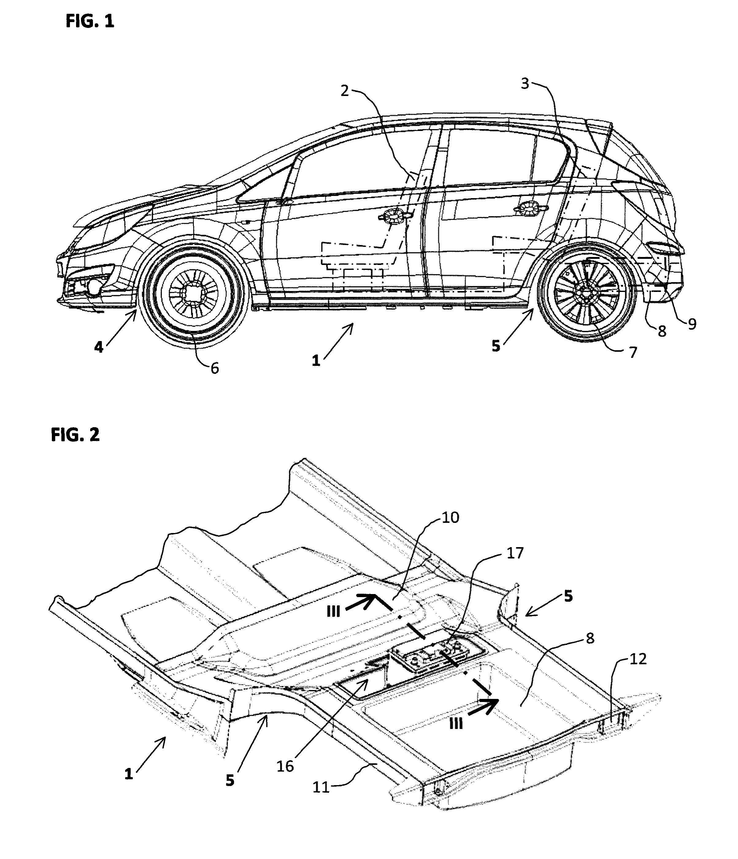
[0025]FIG. 1 shows a motor vehicle with a floor structure 1 and with front seats 2 arranged veering in driving direction and with rear seats 3. The floor structure 1 has wheel arches 4,5 for front and rear wheels 6,7 and a trough 8 for a spare wheel 9.

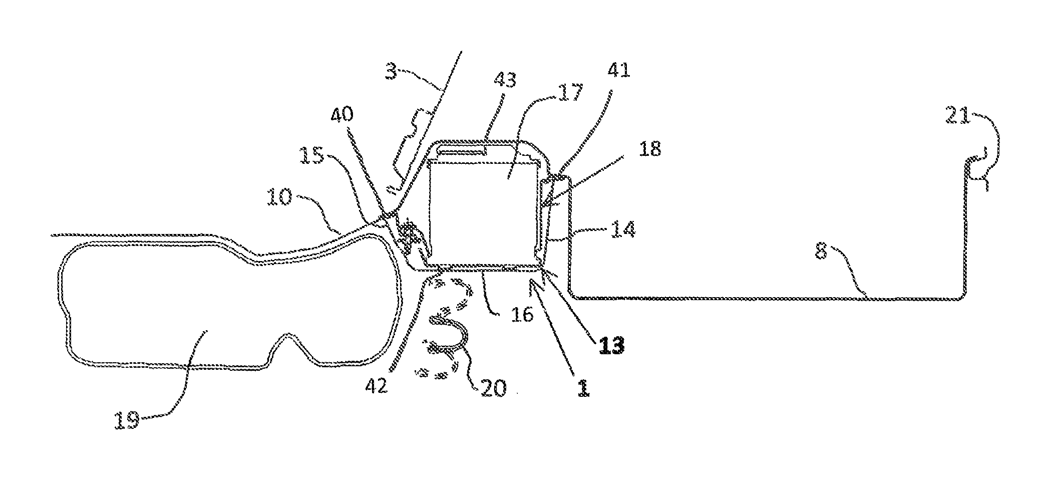
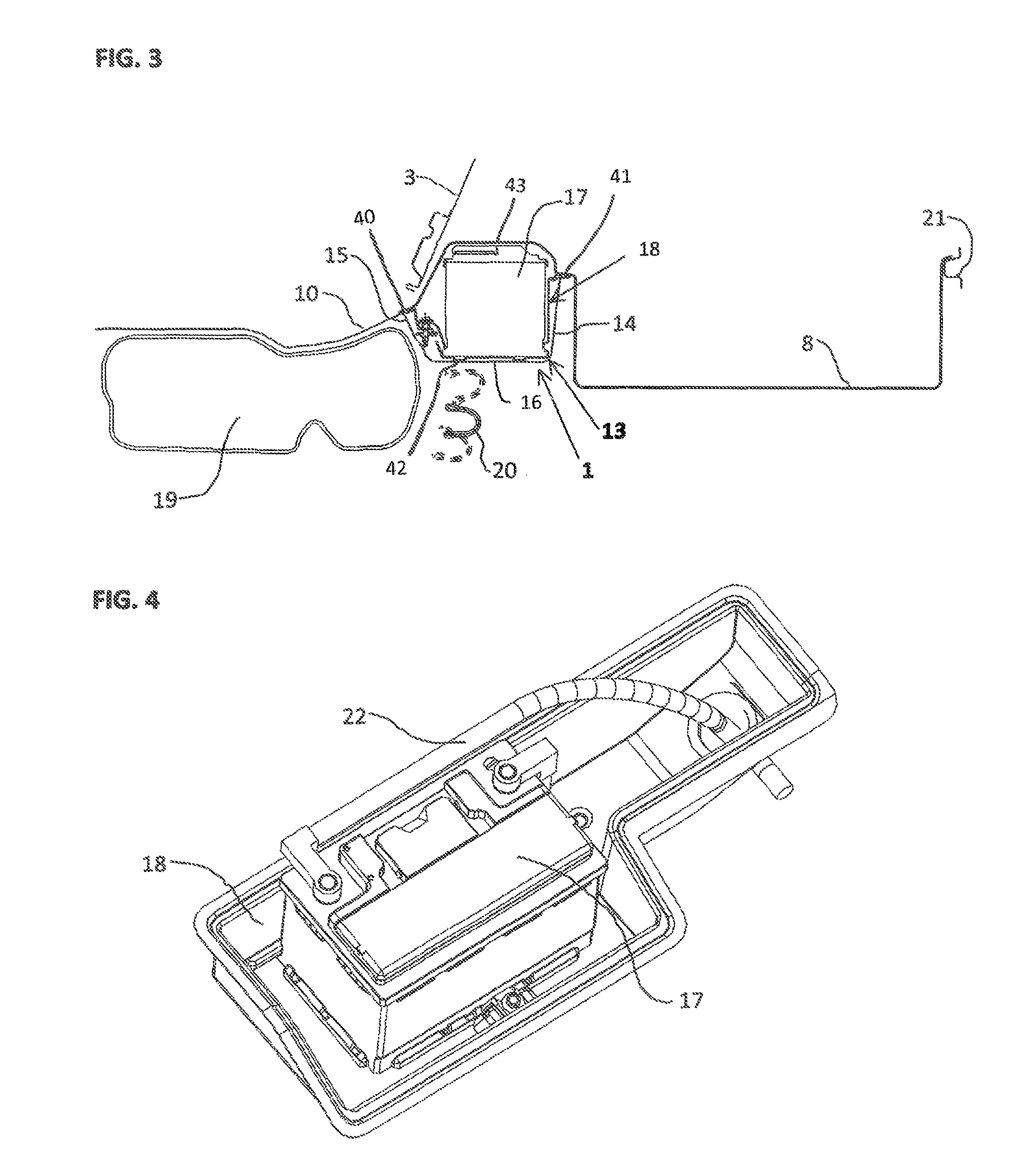
[0026]The floor structure 1 is perspectively shown in FIG. 2. Here it is evident that the floor structure 1 comprises a floor panel 10 and size delimited laterally by side members 11, 12 facing in driving direction. The side members 11,12 are interconnected via a cross member 13 in the region of the rear wheel arches 5 and thus immediately behind the rear seats 3. The cross member 13 is thus located in front of the trough 8 for the spare wheel 9 and comprises two stiffen...


PUM


Abstract

A floor structure of a motor vehicle is provided that includes, but is not limited to a mounting for a starter battery in a cross member adjoining wheel arches for rear wheels. The cross member comprises two stiffening webs and is designed tub-shaped between the stiffening webs. Because of this, the starter battery is reliably protected against a crash.

Description

CROSS-REFERENCE TO RELATED APPLICATION[0001]This application claims priority to German Patent Application No. 102009031779.1, filed Jul. 6, 2009, which is incorporated herein by reference in its entirety.TECHNICAL FIELD[0002]The invention relates to a floor structure for a motor vehicle with side members arranged in driving direction laterally delimiting the floor structure, with a floor panel, with stiffening webs mounted on the floor panel arranged transversely to the driving direction and interconnecting the side members and with wheel arches for front and rear wheels.BACKGROUND[0003]Floor structures are frequently used in modern motor vehicles and are known from practice. Cross members form the stiffening webs with which the floor structure is stiffened. Various components to be arranged in the motor vehicle are usually mounted on rails, brackets or the like fastened to the floor panel. Because of this, the components require a lot of space which particularly in the rear region ...

Claims


Application Information

Patent Timeline
IPC IPC(8): B60R16/04H01M50/249
CPCB60R16/04H01M2/1083B62D25/087Y02E60/10H01M50/249B62D23/00B62D25/20B62D25/2027
Inventor SCHWARZ, MARTINROSENPLANTER, STEPHAN
Owner GM GLOBAL TECH OPERATIONS LLC
Why Eureka
Try Eureka