
Wafer container with elasticity module

a technology of elasticity module and wafer, applied in the field of wafer containers, to achieve the effect of effective fastening of wafers

Active Publication Date: 2013-08-13
GUDENG PRECISION IND CO LTD
View PDF21 Cites 5 Cited by
  • Summary
  • Abstract
  • Description
  • Claims
  • Application Information

AI Technical Summary

Benefits of technology

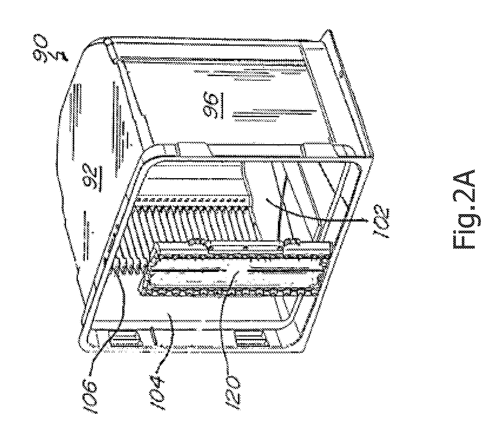
The present invention is a wafer container with an elasticity module that can prevent damage to the wafers during transferring and eliminate the possibility of wafer slipping. The container body has a plurality of slot portions for sustaining the wafers and an elasticity module is disposed on the inner wall of the container body opposite to the opening for effectively fastening the wafers. The elasticity module has a rectangular body with a convex portion bending towards the interior of the container body and an upwardly extending slant portion is formed on the end of each carrying portion of the slant portions near the elasticity module. When the door and opening of the container body are joined, the wafers are raised along with the upwardly extending slant portions. The technical effects of the invention include preventing damage to the wafers, eliminating the possibility of wafer slipping, and providing effective fastening of the wafers.

Problems solved by technology

In the wafer container of the prior art, wafers can be stably placed in the wafer container with the support of wafer contact portions; however, vibration occurring in the wafer transferring process may still cause displacement of wafer or movement of wafer toward the opening which may thus lead to damages.

Method used


Image

  • Wafer container with elasticity module
  • Wafer container with elasticity module
  • Wafer container with elasticity module

Examples


first embodiment

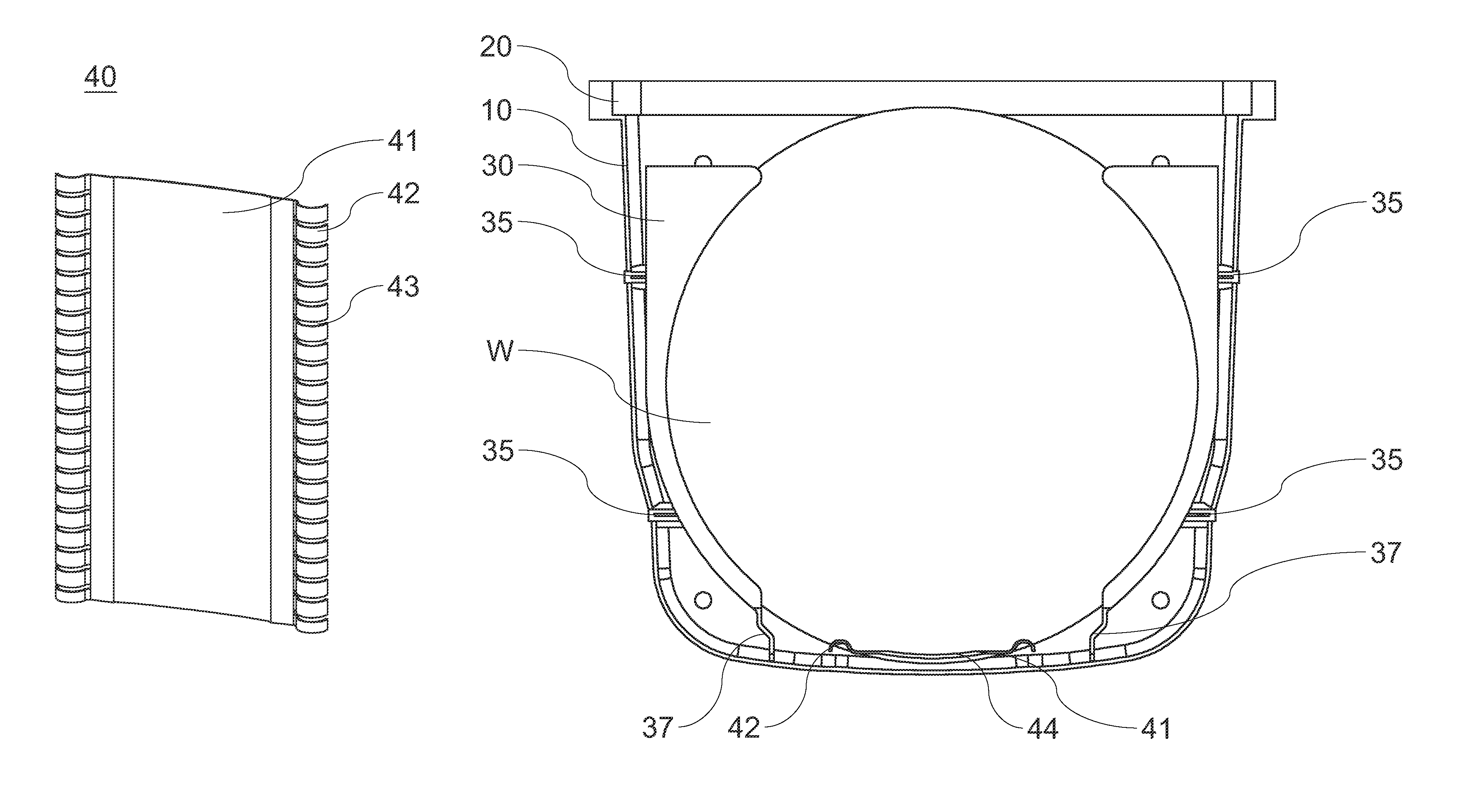
[0031]Referring to FIG. 5A, which is a view of elasticity module of the present invention. The elasticity module 40 has a rectangular body 41, and a convex portion 42 bending toward the interior of the container body 10 and forming a curve is respectively formed on two opposite longer sides of the rectangular body 41, wherein the rectangular body 41 has a curved inwardly recessed portion 44, the top view of the inwardly recessed portion 44 being as shown in FIG. 6A. When the door 20 closes the container body 10, the wafers W are pushed onto the elasticity module 40; meantime, the edges of wafers W are in contact with the convex portion 42 on two sides and extend into the space formed by the inwardly recessed portion 44. Since the elasticity module 40 is elastic, when the edges of wafers W are in contact with the convex portion 42 on two sides, the convex portion 42 will be pressed by wafers W and is slightly deformed; when the door 20 and the container body 10 are disjoined, each of...

third embodiment

[0033]Then, referring to FIG. 5C, which is a view of elasticity module of the present invention. The elasticity module 40 is disposed on the inner wall 14 of the rear end of the container body 10 opposite to the opening 12 and its material is the same as that of the elasticity module 40 of the embodiment previously described. The elasticity module 40 of the present embodiment has a rectangular body 41, and a convex portion 42 bending toward the interior of the container body 10 and forming a curve is respectively formed on two opposite longer sides of the rectangular body 41, wherein a plurality of notches 43 vertically arranged at intervals are disposed on the convex portion 42, a side view of which being as shown in FIG. 6C. Since a wafer container can normally carry 25 wafers W, when the number of notches 43 is 24 in the present embodiment, the convex portions 42 can be divided into 25 sections. In addition, the rectangular body 41 has a curved inwardly recessed portion 44 that c...


PUM


Abstract

A wafer container, comprising: a container body, the container body having a plurality of slot portions on two opposite sidewalls of the interior of the container body for horizontally sustaining a plurality of wafers, each slot portion having a horizontal carrying portion, an opening being formed on one side of the container body for exporting and importing a plurality of wafers; and a door, said door having an inner surface and a outer surface, the inner surface being joined with the opening of the container body for protecting the plurality of wafers therein, the characteristic in that: an elasticity module is disposed on the inner wall of the rear end of the container body opposite to the opening, the elasticity module having a rectangular body and a convex portion bending toward the interior of the container body being respectively formed on two longer opposite sides of the rectangular body.

Description

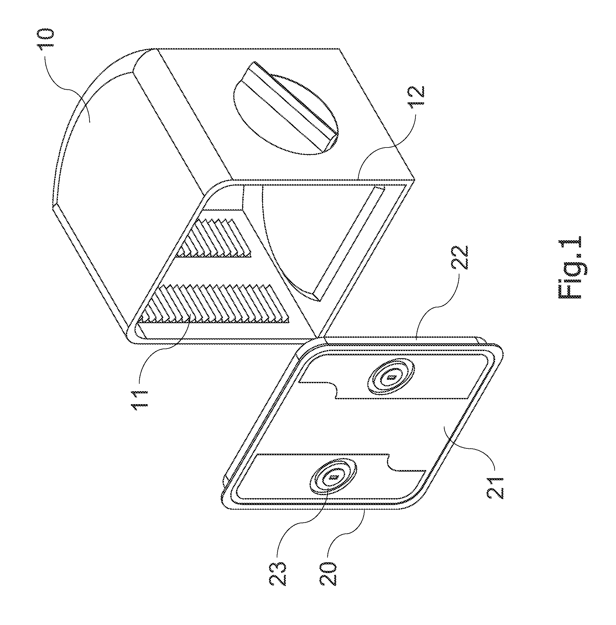
BACKGROUND OF THE INVENTION[0001]1. Field of the Invention[0002]The present invention is related to a wafer container, and more particularly, to a wafer container with its interior being disposed with an elasticity module that provides elastic buffering mechanism to protect the wafers from being damaged due to excessive vibration in the transferring process.[0003]2. Description of the Prior Art[0004]The semiconductor wafers need to be transferred to different work stations to go through various processes in required equipments. In order to facilitate the transferring of wafers and to prevent the pollution of wafers from occurring during transferring process, a sealed container is provided for the automatic transferring process. Referring to FIG. 1, which is a view of wafer container of the prior art. The wafer container includes a container body 10 and a door 20. The container body 10 is disposed with a plurality of slots 11 for horizontally supporting a plurality of wafers (not sho...

Claims


Application Information

Patent Timeline
Patent Type & Authority Patents(United States)
IPC IPC(8): B65D85/00
CPCH01L21/67383H01L21/67369
Inventor LU, SHAO-WEILU, PAO-YIWANG, CHIEN-FENG
Owner GUDENG PRECISION IND CO LTD
Learn More