Retrofit mounting assembly for recessed lighting fixtures

a technology for mounting assemblies and recessed lighting, which is applied in the direction of fixed installation, lighting and heating equipment, lighting support devices, etc., can solve the problems of limited user access, costly and time-consuming to repair or replace lamp components such as ballasts, and difficult access

Active Publication Date: 2013-08-13
HUBBELL LIGHTING INC
View PDF32 Cites 51 Cited by
  • Summary
  • Abstract
  • Description
  • Claims
  • Application Information

AI Technical Summary

Benefits of technology

[0009]Accordingly, one aspect of the invention is to provide a lighting assembly that can be used to retrofit a recessed lighting fixture without the need to remove the existing fixture and where the retrofit lighting assembly is coupled to the existing plaster frame or ceiling structure.
[0010]Another aspect of the invention is to provide a lighting assembly that can be attached directly to a plaster frame or other support structure for a lighting fixture without the need to remove the ceiling, cut access openings or the need to remove the support structure from the ceiling.

Problems solved by technology

Recessed lighting fixtures are typically installed behind a frame or above a ceiling which limits the accessibility to the user.
It can be costly and time consuming to repair or replace lamp components such as ballasts, transformers and other components that are mounted to the lighting assembly.
The replacement lamps often require the replacement of a ballast that is mounted within the wall or ceiling cavity and can be difficult to access without removing the support structure or removing the ceiling tiles or cutting access openings in the wall or ceiling.

Method used


Image

  • Retrofit mounting assembly for recessed lighting fixtures
  • Retrofit mounting assembly for recessed lighting fixtures
  • Retrofit mounting assembly for recessed lighting fixtures

Examples


first embodiment

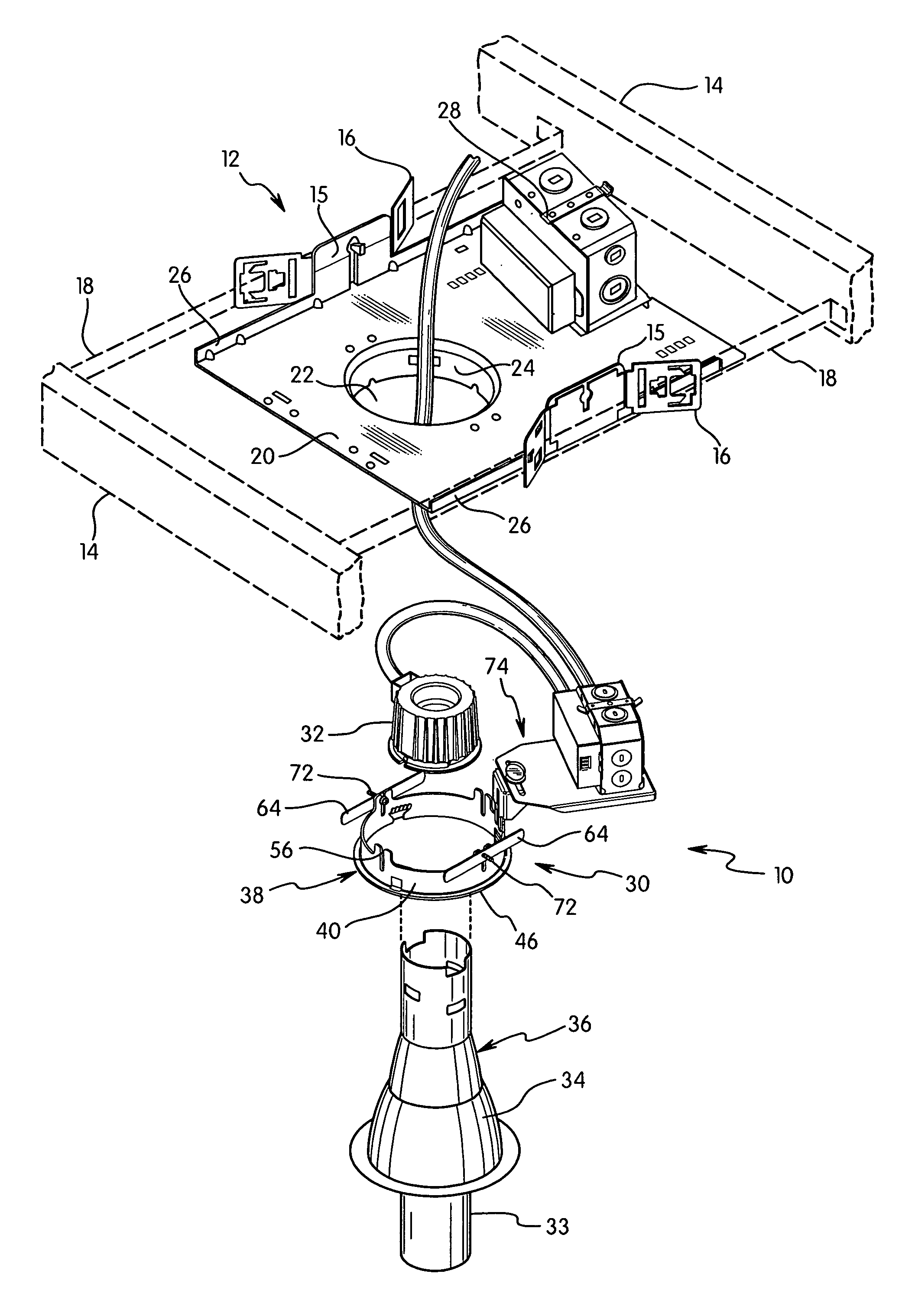
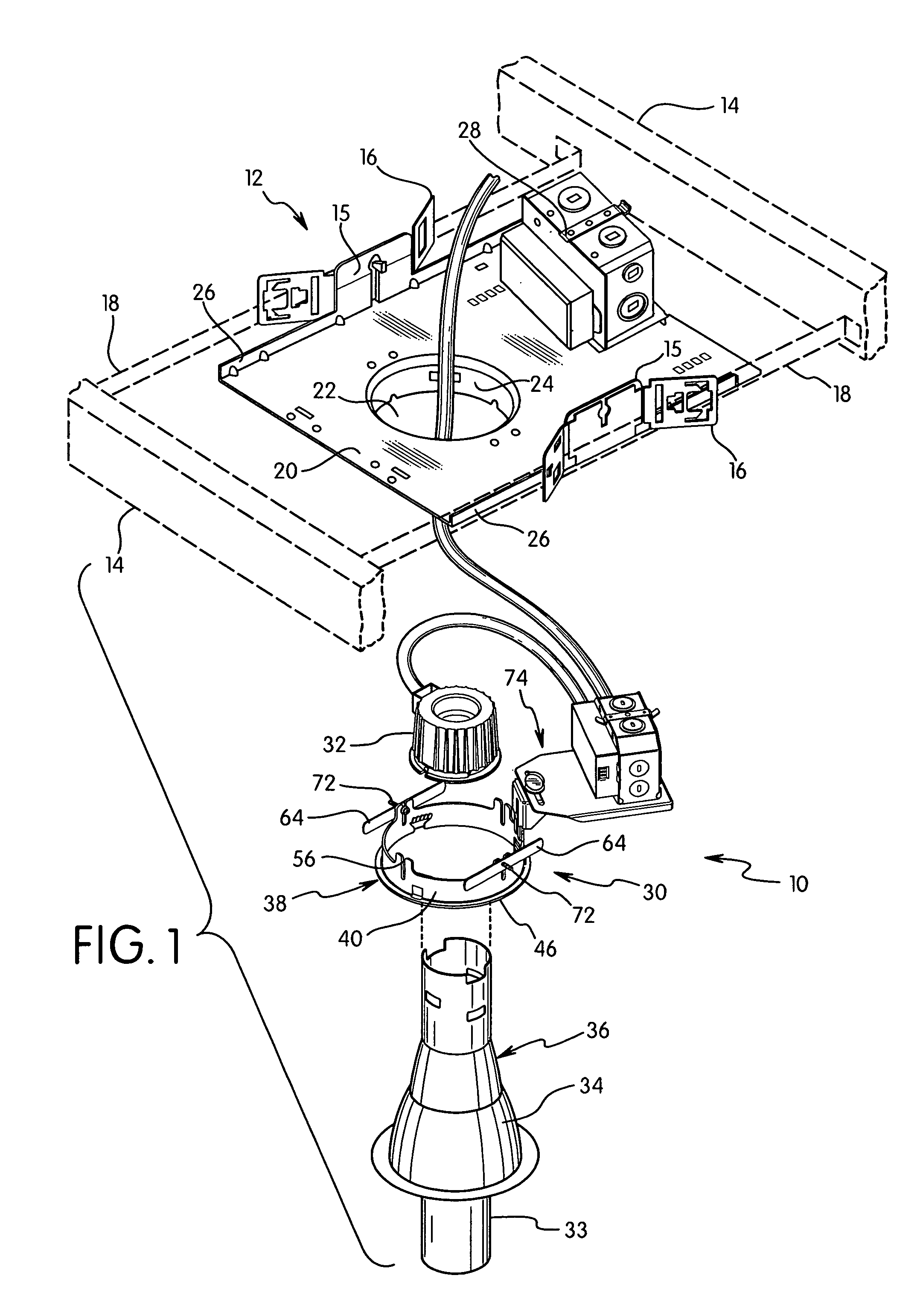
[0043]Referring to FIGS. 1-11, lighting assembly 10 in a first embodiment is a complete and self-contained lighting assembly adapted for retrofitting a mounting frame such as plaster frame 12 or for mounting in an opening in the ceiling. Lighting assembly 10 includes a mounting assembly 30 for receiving and supporting a luminaire 36 that includes lamp socket 32, a lamp and reflector 34. Luminaire 36 preferably has a suitable shape and size to accommodate the plaster frame 12. Lighting assembly 10 can be used to replace damaged parts of the existing luminaire or to upgrade the existing luminaire to more efficient lighting. In one embodiment of the invention, lighting assembly 10 is a LED lighting assembly for upgrading the existing luminaire. In other embodiments, lighting assembly 10 is a compact fluorescent light assembly.

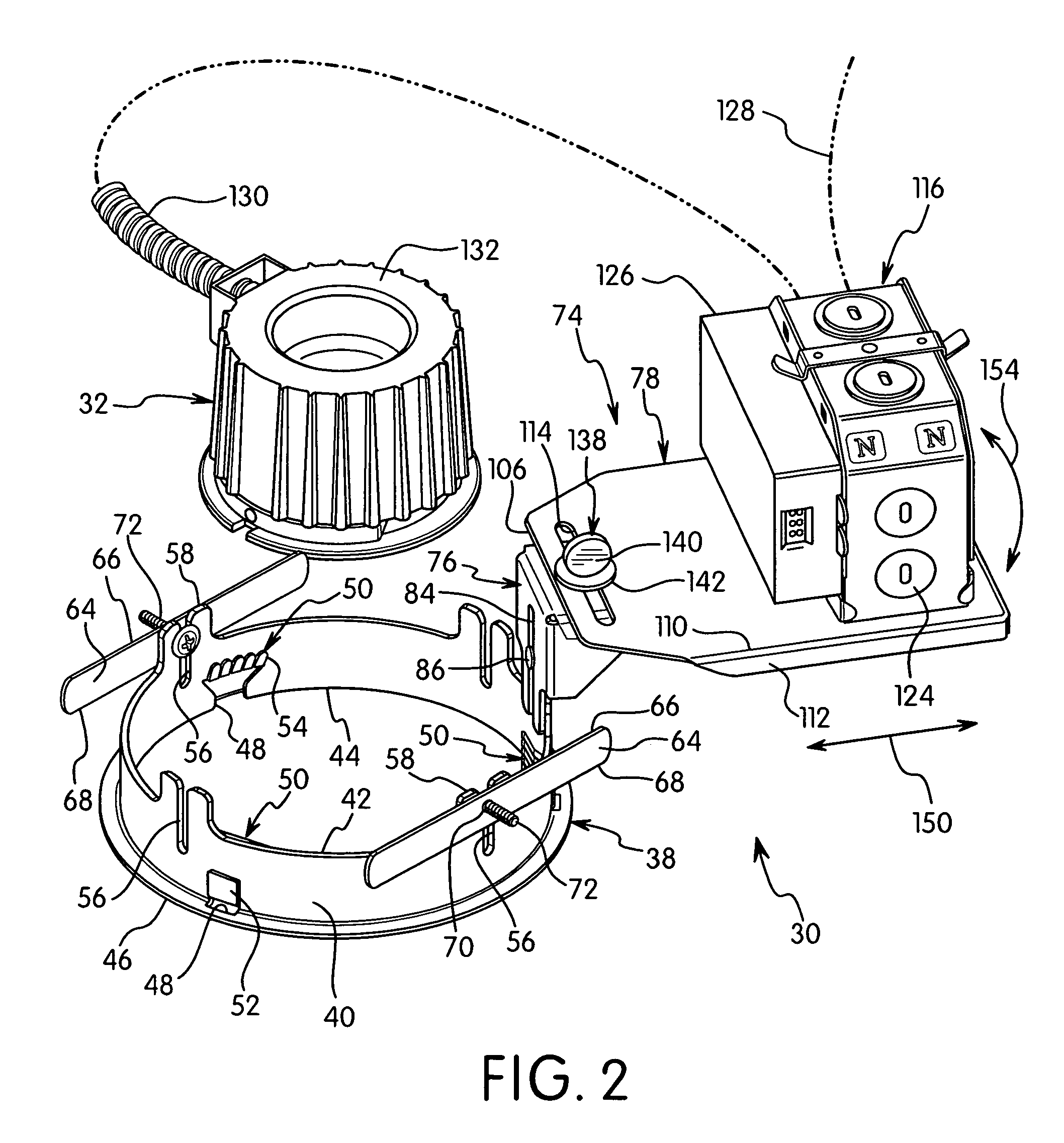
[0044]Mounting assembly 30 in the first embodiment of the invention includes a mounting ring 38 having a dimension for inserting into the opening 22 of plaster fr...

second embodiment

[0063]In a second embodiment shown in FIGS. 12-16, the retrofit lighting assembly 160 includes a mounting ring 162 formed from a first semi-circular ring portion 164 and a second semi-circular ring portion 166. The mounting assembly 30 for the electrical junction box and the socket for the retrofit luminaire are substantially the same as in the previous embodiment. Thus, the components of the mounting assembly 30 are shown in FIG. 12 by the same reference numbers.

[0064]As shown in FIG. 12, first portion 164 and second portion 166 have a semicircular shape that are joined together at respective ends 168 in an overlapping manner. The overlapping ends can be coupled together by a screw or other fastener although it is not essential that the ends be mechanically coupled together. As shown in FIG. 13, second ring portion 166 has a recessed area 167 at the ends 168 with a dimension to receive the ends of the first ring portion 164. The recessed areas 167 are formed to enable the side wall...


PUM


Abstract

A retrofit luminaire assembly is provided for retrofitting a mounting frame such as a plaster frame or other recessed lighting assembly without the need to remove the existing plaster frame. The retrofit assembly includes a mounting ring that can support a replacement electrical junction box and the replacement luminaire. The mounting ring is inserted through the opening in the plaster frame and secured to the plaster frame by an attachment member that engages the top face of the plaster frame. The attachment member can include a plate coupled to the mounting ring to form two outwardly extending arms. The plate is axially adjustable with respect to the mounting ring to clamp the plaster frame between the plate and the bottom flange of the mounting ring. In another embodiment, the attachment member has a hook-like end that engages a bottom surface of the mounting frame.

Description

FIELD OF THE INVENTION[0001]The present invention is directed to a mounting assembly for retrofitting a recessed lighting assembly. In particular, the invention is directed to a retrofit assembly having an attachment member for mounting the assembly to a plaster frame or ceiling of a recessed lighting assembly.BACKGROUND OF THE INVENTION[0002]Recessed lighting fixtures are typically installed behind a frame or above a ceiling which limits the accessibility to the user. It can be costly and time consuming to repair or replace lamp components such as ballasts, transformers and other components that are mounted to the lighting assembly. Typically, modifications to an installed lighting assembly require removal of the assembly or various components from the ceiling.[0003]Recently, there has been an increased interest in retrofitting existing recessed light assemblies. Often the retrofit is to upgrade the lighting components and to replace the existing components with more energy efficie...

Claims


Application Information

Patent Timeline
Patent Type & Authority Patents(United States)
IPC IPC(8): F21V17/00
CPCF21S8/026F21V21/04F21V21/048F21V23/026
Inventor WILSON, CARL W.D'ANDREA, RICHARD L.
Owner HUBBELL LIGHTING INC
Why Eureka
Try Eureka