Mobile device with cushion devices

Active Publication Date: 2013-08-13
SUPERIOR COMM
View PDF52 Cites 117 Cited by
  • Summary
  • Abstract
  • Description
  • Claims
  • Application Information

AI Technical Summary

Benefits of technology

[0005]The case disclosed herein is intended to address the need in the art identified by the inventors for greater impact resistance for a mobile device. The case is designed to provide enhanced anti-shock and vibration reduction ca

Problems solved by technology

In addition, the increased amount of time that an individual spends holding a mobile device may increase the probability that the individual drops a mobile device.
Cases that merely protect mobile devices from dirt and scratches may be insufficient to protect the device from impact applied directly to the case.
In addition, the variety of environments in which

Method used


Image

  • Mobile device with cushion devices
  • Mobile device with cushion devices
  • Mobile device with cushion devices

Examples


Example

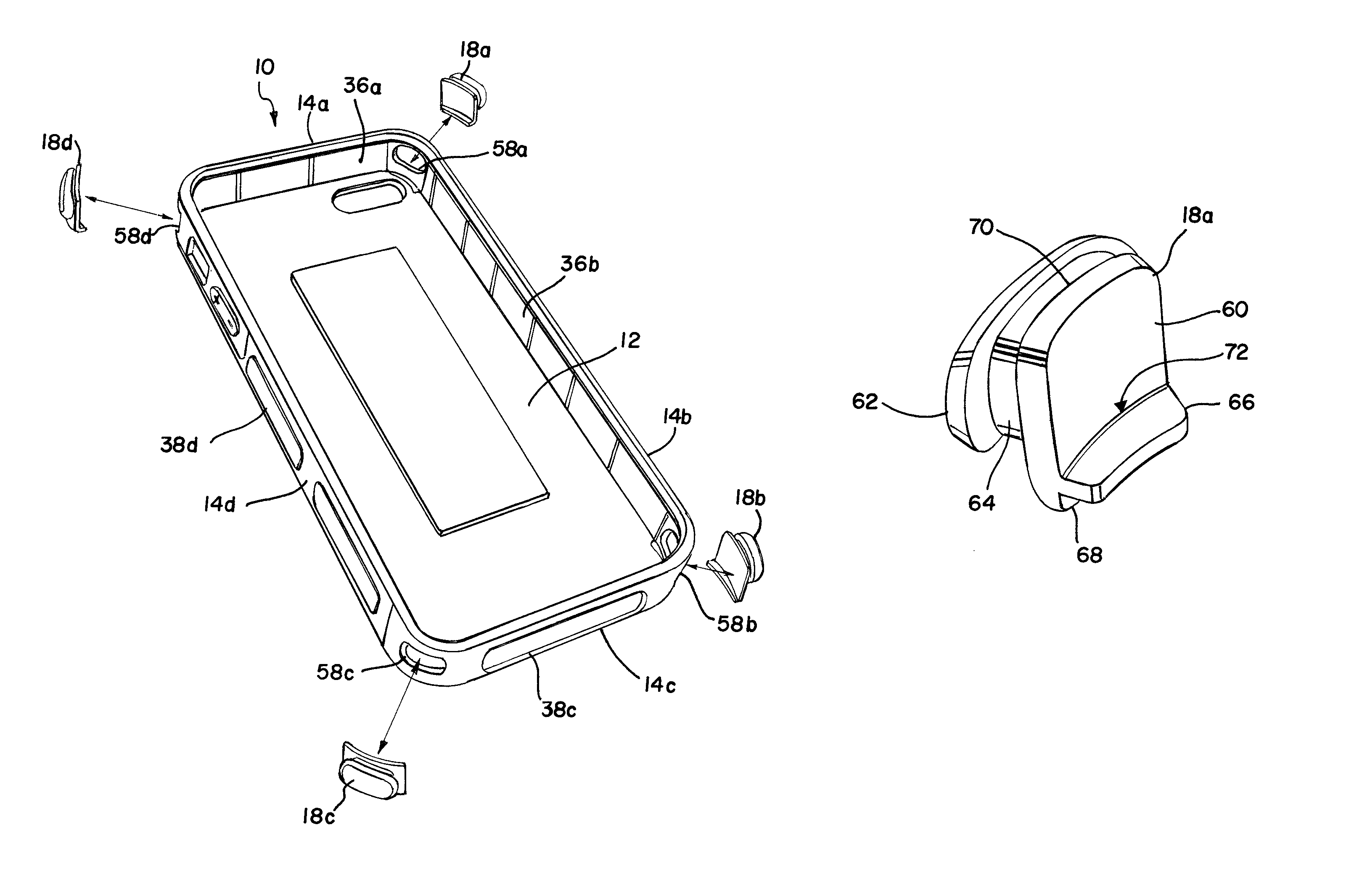
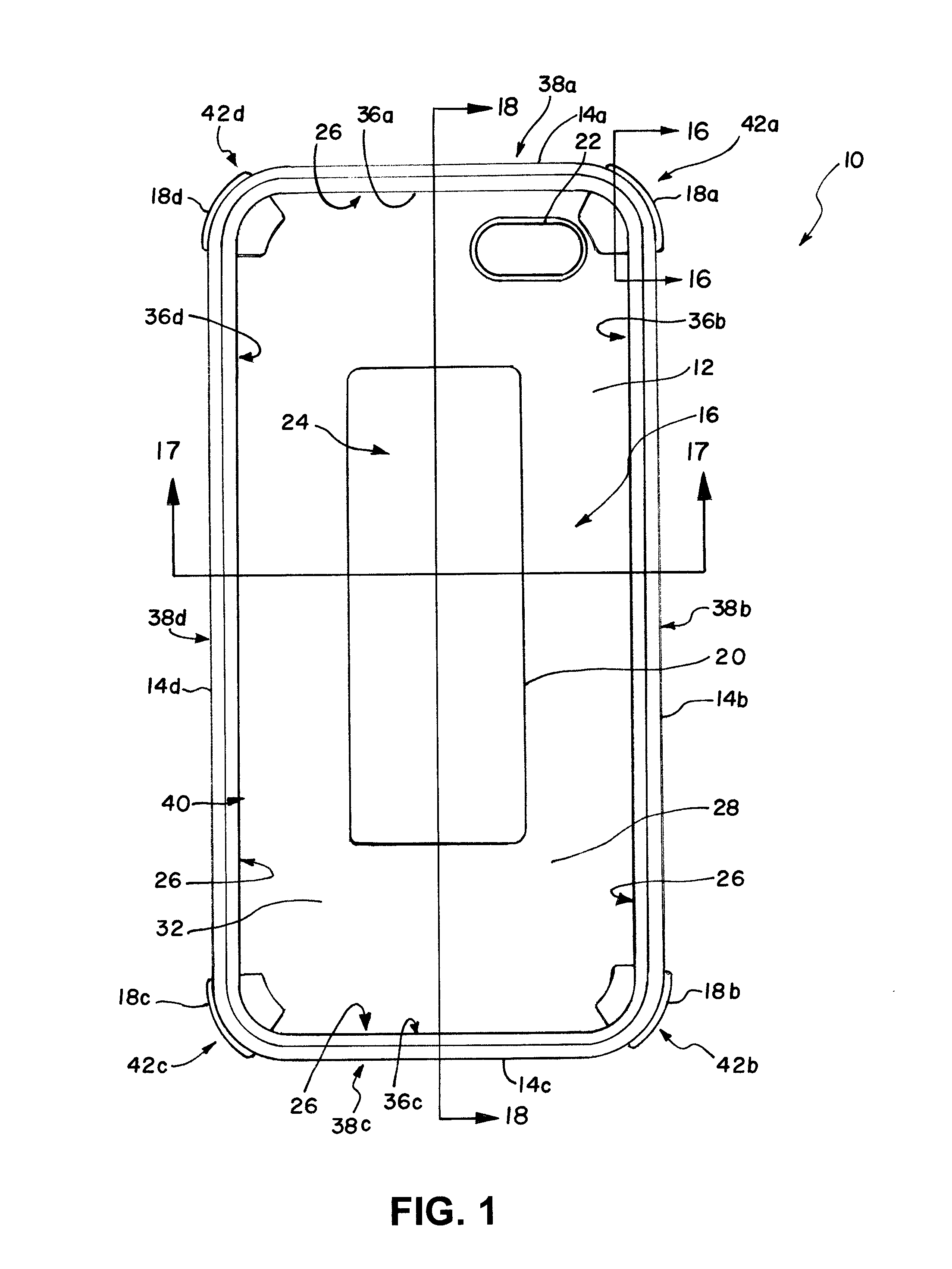
[0033]FIG. 1 illustrates a front view of a case 10 for a mobile device. The case 10 includes a base wall 12 and a plurality of side walls 14a-d (referred to collectively as 14). The side walls 14 extend away from the base wall 12 to form a recess 16 configured to receive the mobile device. A plurality of cushion devices 18a-d (referred to collectively as 18) extend through the side walls 14. A cushion device 20 is positioned upon the base wall 12. An aperture 22 is positioned on the base wall 12.

[0034]The base wall 12 is a covering that covers a surface of the mobile device that is received by the recess 16. The base wall 12 extends out from a central portion 24 of the case 10 to outer portions 26 of the case 10 to form the covering.

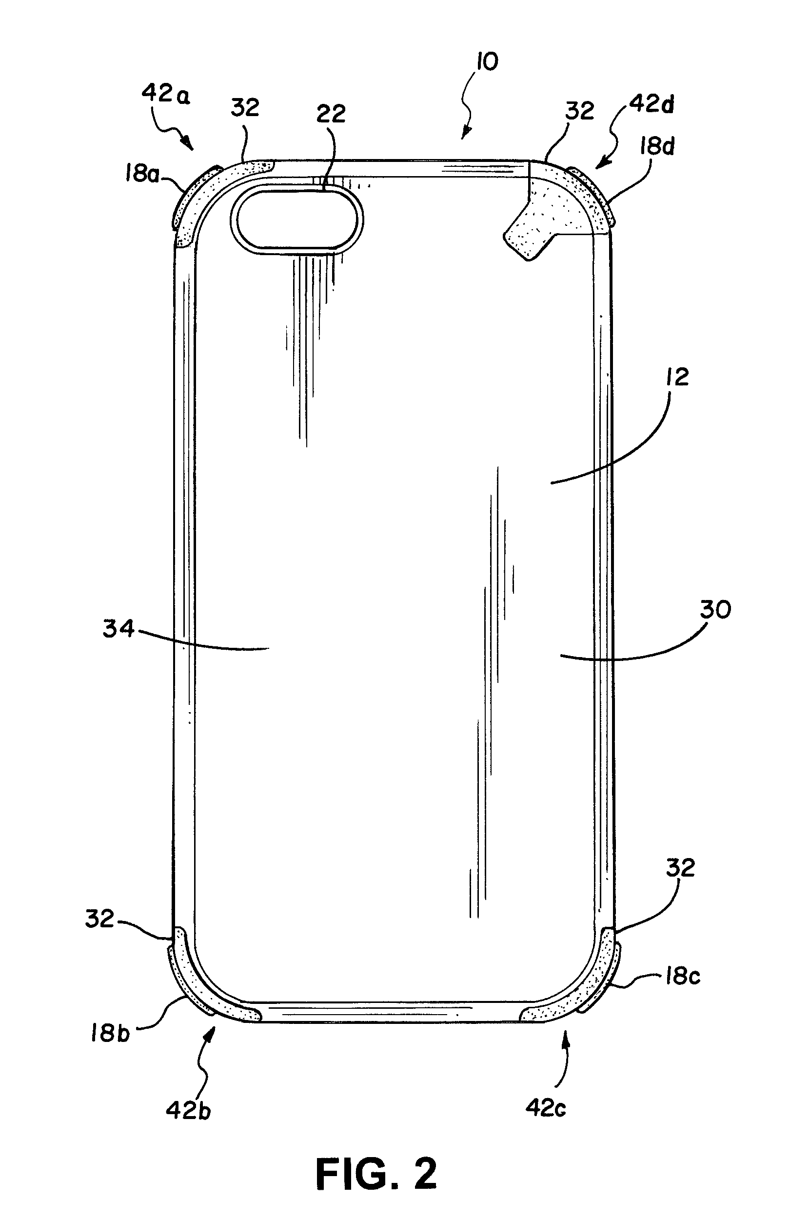
[0035]The base wall 12 includes an inner surface 28 and an outer surface 30 (shown in FIG. 2). The inner surface 28 faces towards the mobile device when the mobile device is received in the recess 16. The outer surface 30 faces away from the mobile devic...


PUM


Abstract

A case for a mobile device including a base wall and a plurality of side walls extending from the base wall to cover side surfaces of the mobile device. A plurality of cushion devices may pass through the side surfaces to cushion the mobile device from a force exerted upon the case.

Description

FIELD OF THE INVENTION[0001]The present disclosure relates to protective cases for mobile devices.BACKGROUND OF THE INVENTION[0002]Mobile devices, in the form of phones, computers, digital assistants, and hand held devices have become commonplace in society. Cellular phones, for example, are now carried by individuals at work, at home, at play, and in a variety of other environments. The increased range of wireless communication coverage enhances the variety of environments in which wireless-enabled mobile devices may be used. It may not be unusual to see a mobile device used while an individual is at the beach, at the mall, near a river, walking over a rocky surface, or hiking up a mountain.[0003]Cases have been developed that protect mobile devices from dirt and scratches that may accumulate from normal use. The cases may comprise a shell or other covering that extends over the mobile device so that dirt does not enter crevices of the mobile device, or so the outer finish of the d...

Claims


Application Information

Patent Timeline
IPC IPC(8): H04M1/00
CPCH04M1/04H04B1/3888H04M1/185A45C2011/002A45C13/36
Inventor LACOLLA, CHARLIECHOU, VIVIANPAN, JASONPATEL, SHRADDHA
Owner SUPERIOR COMM
Why Eureka
Try Eureka