Superconducting cable and superconducting cable line using the same

Inactive Publication Date: 2006-12-19
SUMITOMO ELECTRIC IND LTD
View PDF13 Cites 12 Cited by
  • Summary
  • Abstract
  • Description
  • Claims
  • Application Information

AI Technical Summary

Benefits of technology

[0023]In the superconducting cable of the present invention, by deliberately providing a portion whose critical current value is differentiated, damage due to short-circuit failure may occur at the portion only, and the occurrence of such damage to all over the superconducting cable can be restrained. Thus, the possibility of overall damage to the cable can be reduced. Furthermore, in case of a short-circuit failure, a damaged portion can be easily predetermined. In the superconducting cable line using the superconducting cable of the present inventi

Problems solved by technology

When a short-circuit failure occurs in a normal conducting cable, a large current flows in the conductor.
However, since a superconducting conductor forming the superconducting layer generally is expensive, it is difficult in view of cost-effectiveness to increase the margin with respect to the critical current value Ic.
That is, so-called “quenching” occurs to cause the superconducting layer to generate heat, and the superconducting cable may be damaged due to an incre

Method used


Image

  • Superconducting cable and superconducting cable line using the same
  • Superconducting cable and superconducting cable line using the same
  • Superconducting cable and superconducting cable line using the same

Examples


Example

EXAMPLE 1

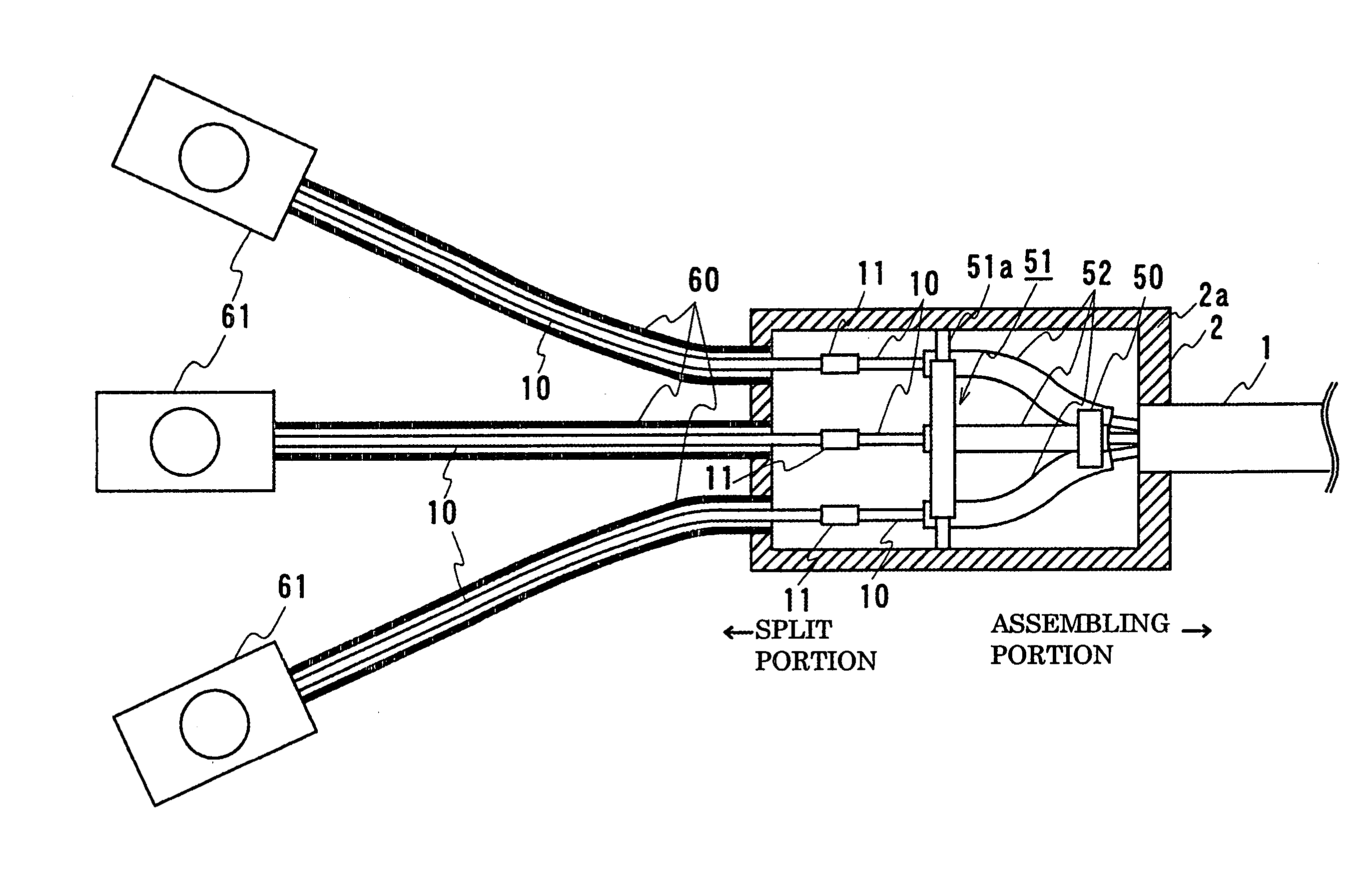
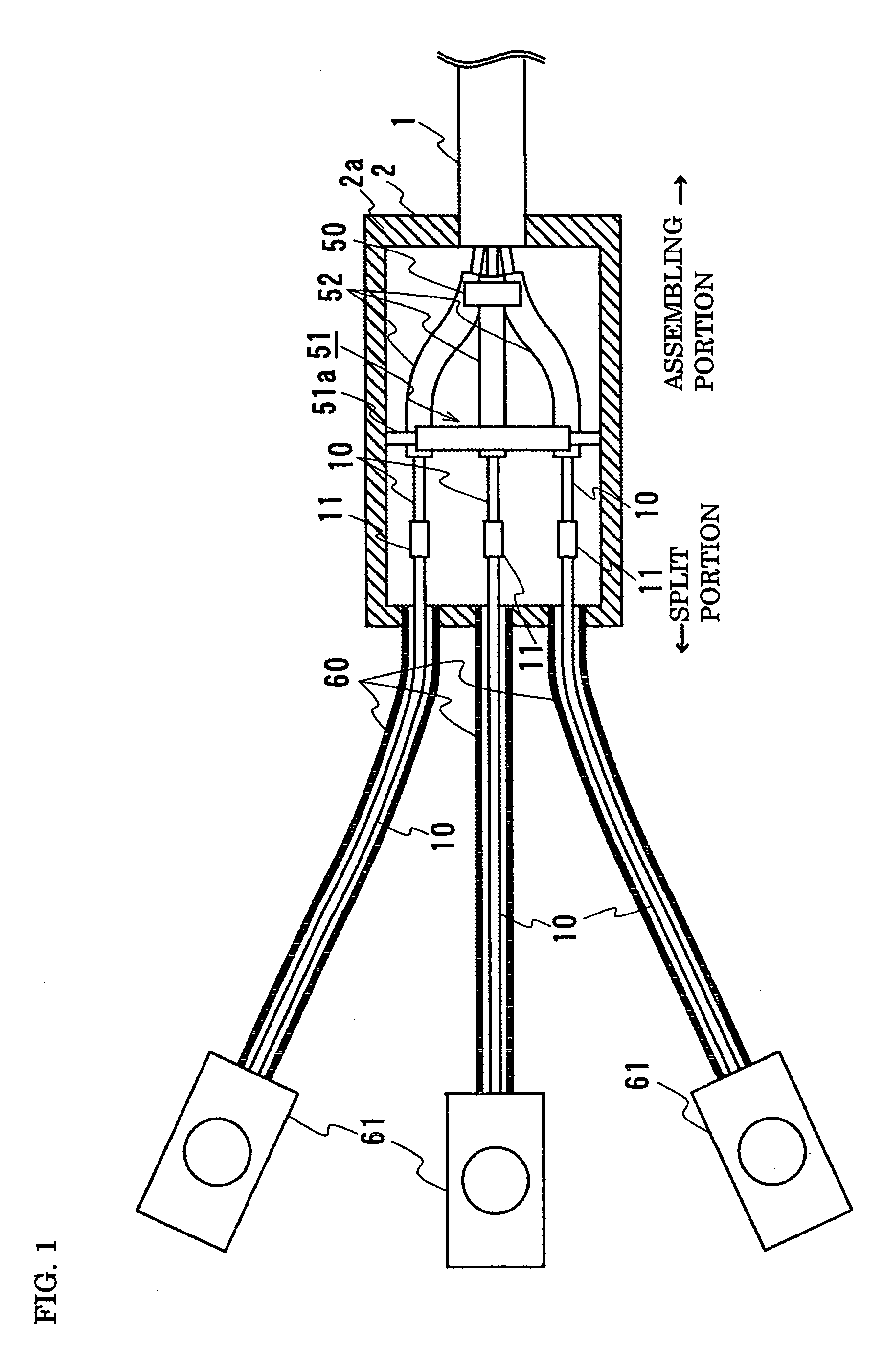
[0037]FIG. 1 is a schematic diagram illustrating a terminating portion of a cable line having a superconducting cable of the present invention; their current limiting portions 11 are located in a termination joint box 2. A description of a first example and a second example, which appears below, is given in the context of a three-core superconducting cable 1 formed by stranding three cable cores 10, as shown in FIGS. 1 and 2.

[0038]The basic configuration of the superconducting cable 1 is similar to that of the superconducting cable 100 shown in FIG. 3. More specifically, the superconducting cable 1 is formed such that the three cable cores 10, each including, sequentially from the center, the former 200, a superconducting conductor layer 20, the electrical insulating layer 202, a shielding layer 21, and the protective layer 204, are stranded and housed in the thermal insulation pipe 101. The former 200 was formed by stranding a plurality of copper wires each covered with an...

Example

EXAMPLE 2

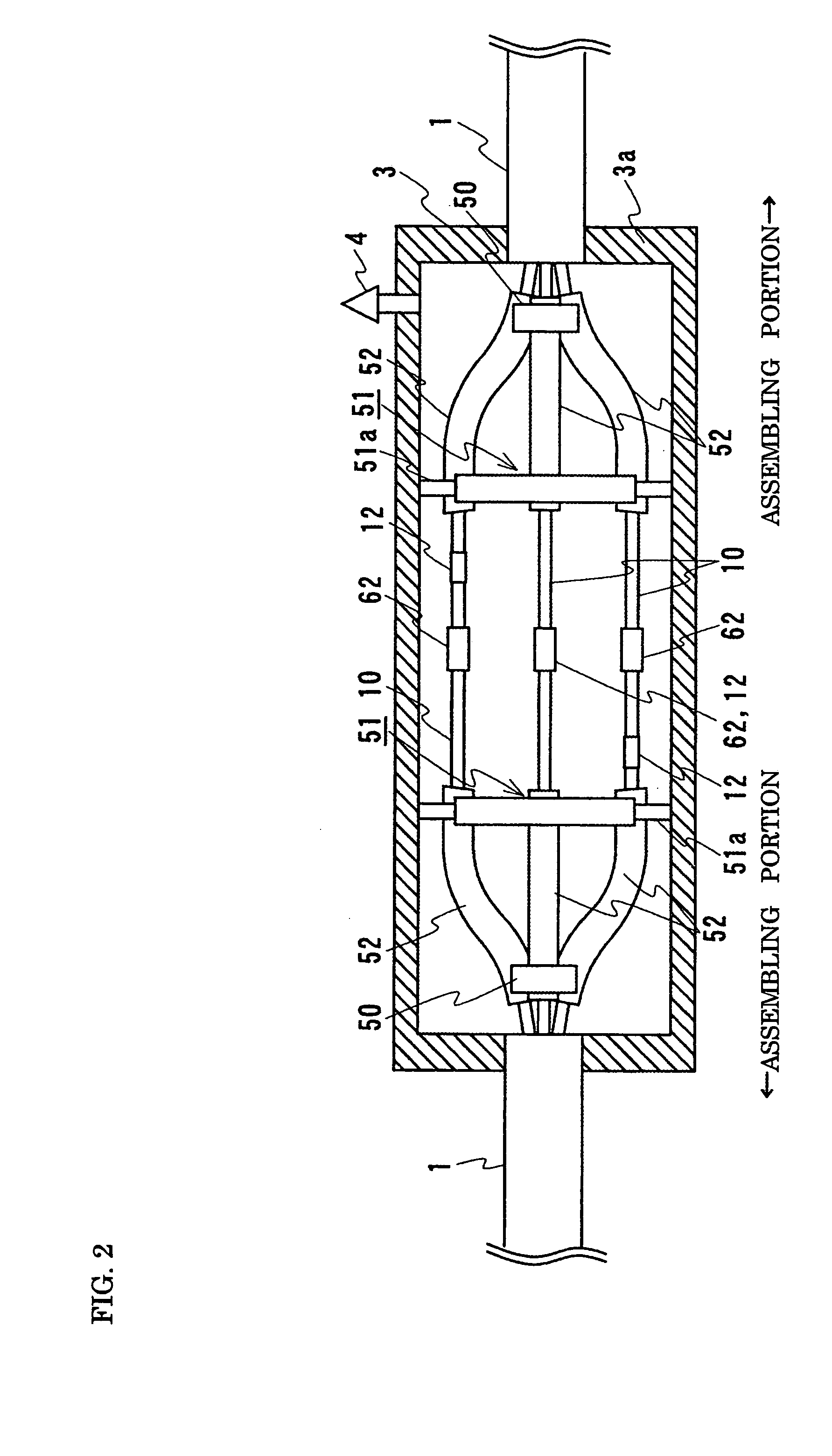
[0051]FIG. 2 is a schematic diagram illustrating an intermediate junction of a cable line having the superconducting cable 1 of the present invention; a limiting portion 12 is disposed within an intermediate joint box 3. The basic configuration of the superconducting cable 1 of the second example is similar to that of the first example shown in FIG. 1 in that the current limiting portions 12 having a smaller critical current than the other portions (normal portion) are provided for the superconducting layers of each cable core 10. However, the configuration of the current limiting portions 12 is different from that of the current limiting portions 11 of the first example, and the current limiting portions 12 are housed in the intermediate joint box 3. The second example is described below mainly in the context of these differences.

[0052]In this example, in two of the three cable cores 10, the current limiting portions 12 were formed by differentiating the number of supercon...


PUM

PropertyMeasurementUnit
Pressureaaaaaaaaaa
Currentaaaaaaaaaa
Contraction enthalpyaaaaaaaaaa

Abstract

Provided is a superconducting cable having a structure such that cable cores, each having a superconducting layer, are housed in a thermal insulation pipe and the superconducting layer of each cable core has portions having different critical current values. When an excessive current flows in the superconducting layer in case of a short-circuit failure, the current exceeds the critical current value of the portion having a smaller critical current value first, which results in damage to the portion, suppressing the occurrence of damage to the other normal portion. A superconducting cable line using this superconducting cable and a splitter for accommodating the cable cores therein is also provided.

Description

BACKGROUND OF THE INVENTION[0001]1. Field of the Invention[0002]The present invention relates to a superconducting cable and a superconducting cable line including the superconducting cable. More particularly, the invention relates to a superconducting cable in which damage caused by a failure, for example, a short-circuit failure, can be reduced, and also relates to a superconducting cable line using this type of superconducting cable.[0003]2. Description of the Related Art[0004]Superconducting cables having a superconducting cable conductor formed of, for example, Bi-based high critical temperature (Tc) superconducting tapes, are known (see, for example, Japanese Unexamined Patent Application Publication No. 2001-325836). FIG. 3 is a sectional view illustrating a three-core three-phase superconducting cable 100 incorporating a plurality of cable cores 102. In this superconducting cable 100, the three cable cores 102 are stranded and housed in a thermal insulation pipe 101.[0005]Th...

Claims


Application Information

Patent Timeline
IPC IPC(8): H01B12/00H01L39/16H01B12/02H01R4/68H02G15/34
CPCH01B12/02H01R4/68H02G15/34Y10T29/49014Y02E40/641Y02E40/648Y02E40/60E04H12/2292C09D5/22F21V21/116F21S8/085F21W2131/103
Inventor FUJIKAMI, JUN
Owner SUMITOMO ELECTRIC IND LTD
Why Eureka
Try Eureka