

Liquid crystal module
- Summary
- Abstract
- Description
- Claims
- Application Information
AI Technical Summary
Benefits of technology
Problems solved by technology
Method used
Image

Examples
first embodiment
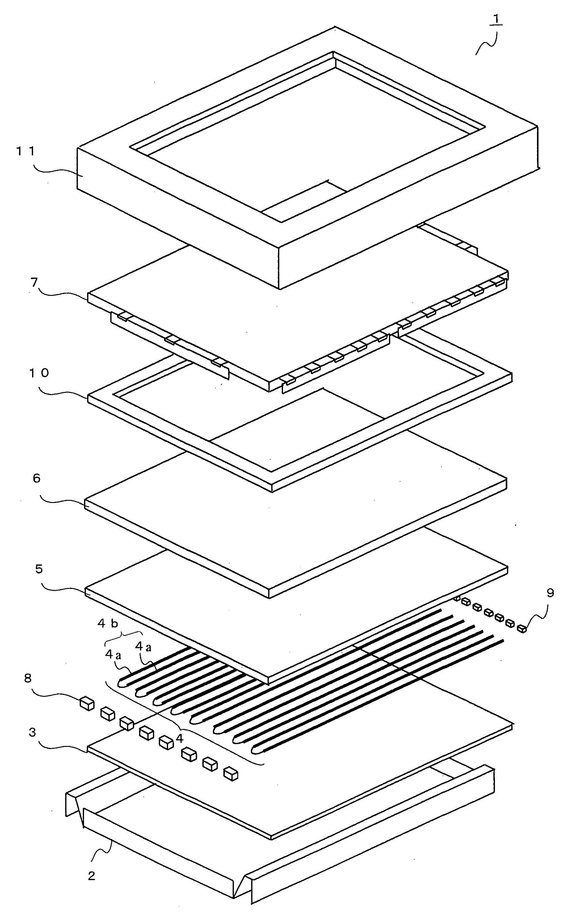
[0035]FIG. 1 is an exploded perspective view to show structure of a liquid crystal module according to a first embodiment. With reference to FIG. 1, total structure of the liquid crystal module 1 according to the first embodiment will be explained. The liquid crystal module 1 according to the first embodiment is provided with a rear frame 2, a reflection sheet 3, a back light source 4, a diffusion plate 5, an optical sheet 6, and a liquid crystal cell 7.
[0036]The rear frame 2 is formed from metal and it has structure in that the reflection sheet 3 and the back light source 4 can be housed. The reflection sheet 3 is formed of a white synthetic resin plate having insulating property, which is put on the rear frame 2. The reflection sheet 3 is included to reflect light which is emitted from the back light source 4.
[0037]The back light source 4 is composed of a plurality of line light sources 4a which are gathered together. In the liquid crystal module 1 according to the first embodimen...
second embodiment
[0065]Next, explanation will be given about a liquid crystal module according to a second embodiment. The liquid crystal module according to the second embodiment has different structure to prevent rotation of the relay board when fastening or loosening of the screws is performed in comparison with the liquid crystal module 1 according to the first embodiment, however, other structures are as same as the liquid crystal module 1 according to the first embodiment. Therefore, portions which are common to the first embodiment are referred to with the same reference numerals and explanation for them will be omitted if not necessary.
[0066]FIG. 5 is a schematic plan view of a liquid crystal module 51 according to the second embodiment when viewed from a front side, it shows a state where bezel 11 (See, FIG. 1) is not attached for the sake of convenience of explanation. FIG. 6 is a schematic plan view of a portion which is surrounded by dotted ellipse in FIG. 5 when viewed from position VI....
PUM
 Abstract
Description
Claims
Application Information