Press die

Active Publication Date: 2014-12-04
TOYOTA BOSHOKU KK
View PDF3 Cites 6 Cited by
  • Summary
  • Abstract
  • Description
  • Claims
  • Application Information

AI Technical Summary

Benefits of technology

The objective of this patent is to create a press die that can prevent damage to the corners of adjacent die blocks during the pressing of a workpiece.

Problems solved by technology

In the press machine disclosed in Japanese Laid-Open Patent Publication No. 2008-296262, it is difficult to position the die blocks of the lower die on the base while maintaining clearances between the die blocks without causing any displacement.
Further, although Japanese Laid-Open Patent Publication No. 2008-296262 discloses that the clearances between the die blocks absorb thermal expansion of the die blocks, the document does not suggest a function for preventing the corner sections of the die blocks from being damaged by striking each other during pressing.

Method used


Image

  • Press die
  • Press die
  • Press die

Examples


Embodiment Construction

[0024]A press die apparatus having press dies according to one embodiment of the present invention will now be described with reference to FIGS. 1 to 6.

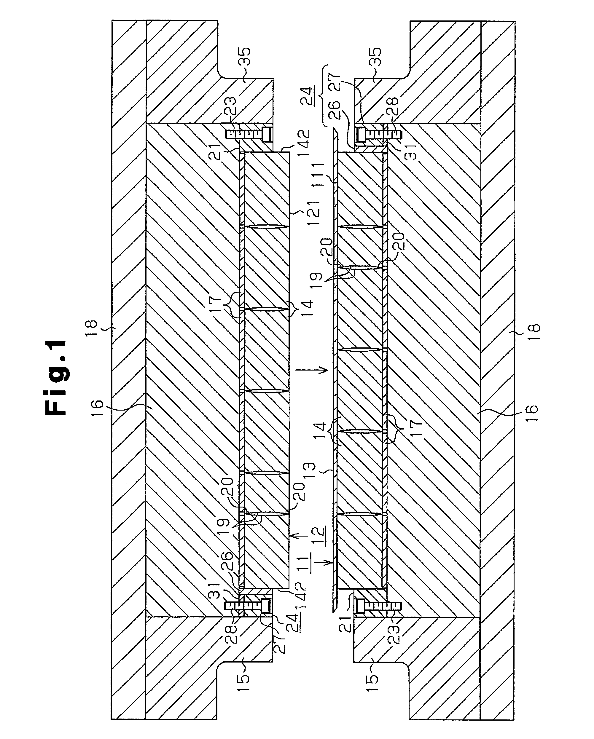
[0025]As shown in FIG. 1, the press die apparatus of the present embodiment includes a lower die 11 and an upper die 12, which are press dies. The upper die 12 is arranged above the lower die 11 to be brought toward and away from the lower die 11. The lower die 11 has on the upper surface a die surface 111, and the upper die 12 has on the lower surface a die surface 121, which has a shape corresponding to the die surface 111 of the lower die 11. With a workpiece 13 placed on the die surface 111 of the lower die 11, the upper die 12 is brought toward the lower die 11 to press the workpiece 13 into a predetermined shape between the die surfaces 111, 121 of the dies 11, 12.

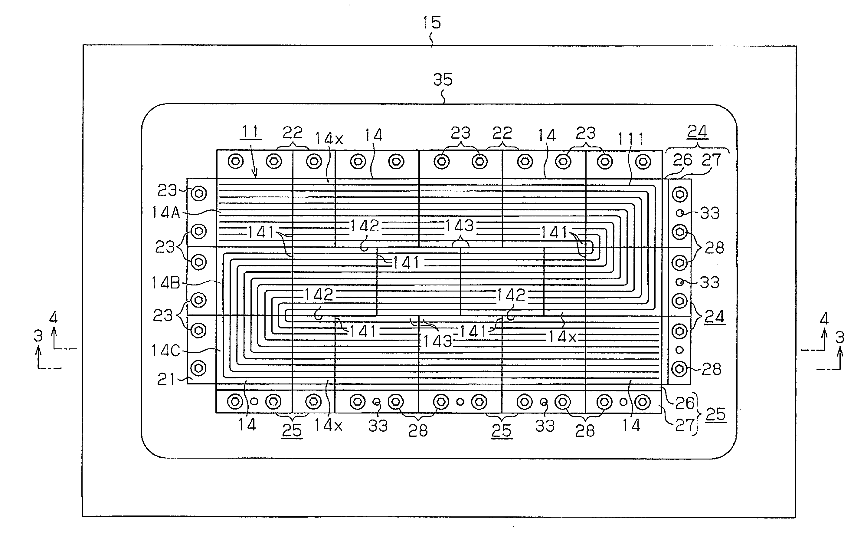
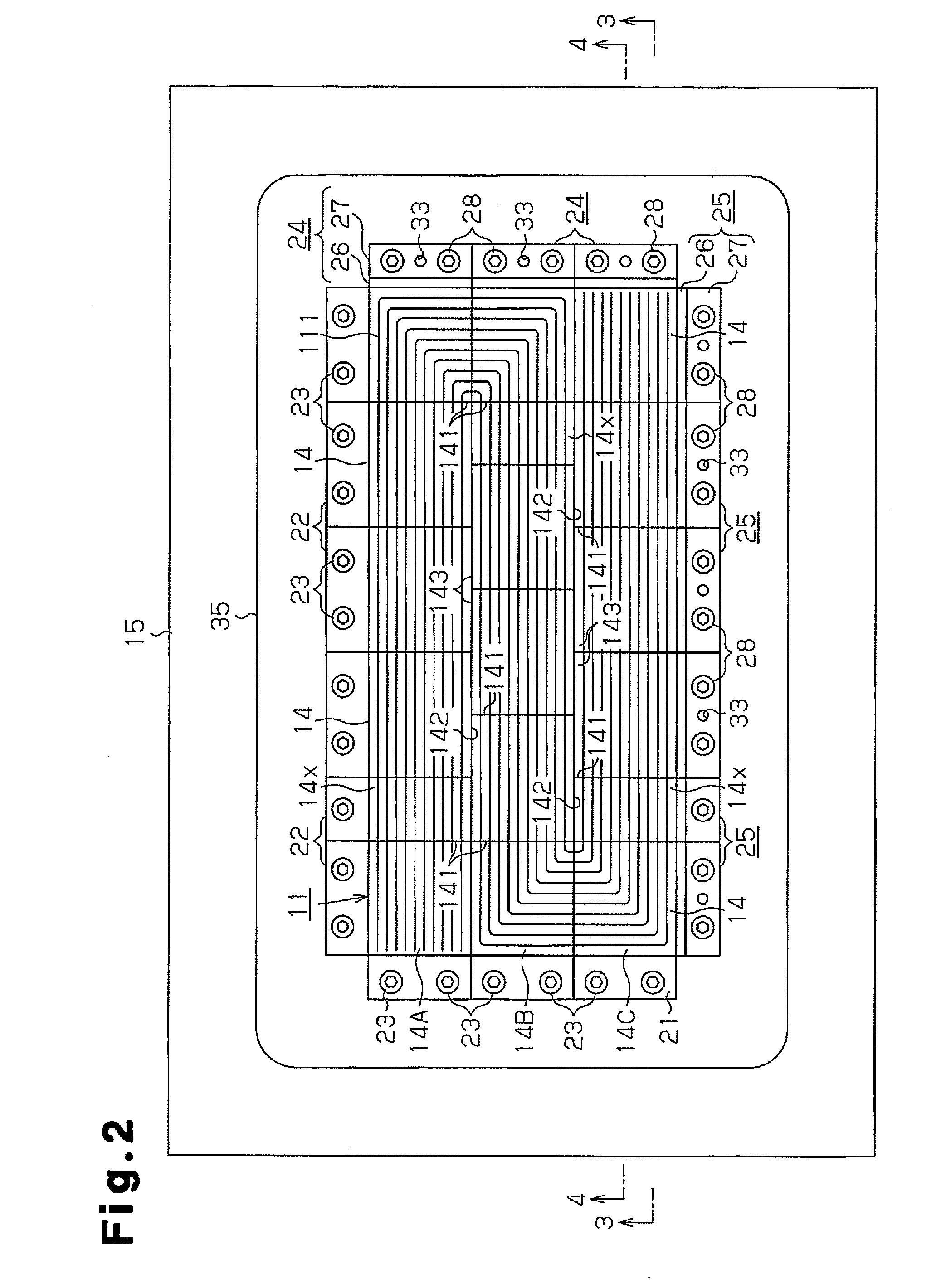
[0026]As illustrated in FIGS. 1 and 2, the lower die 11 is formed by die blocks 14, which are separate rectangular columns. The die blocks 14 are arranged in a frame ...


PUM


Abstract

A press die includes block rows arranged in parallel in a frame. Each block row is formed by die blocks. The block rows include a first block row and a second block row that are adjacent to each other. A joint portion between adjacent two blocks belonging to the first block row faces a side surface of a die block belonging to the second block row.

Description

BACKGROUND OF THE INVENTION[0001]The present invention relates to a press die that is used for forming, for example, a separator for a fuel cell.[0002]A typical separator for a fuel cell has a structure, for example, as shown in FIG. 7. The separator is formed of a plate 41 made of a hard material, such as titanium. The plate 41 has on its surface multiple grooves 42a at predetermined intervals. The plate 41 also has on its back grooves 42b, each of which is located between adjacent two of the above grooves 42a. The grooves 42a, 42b function as gas passages through which hydrogen gas and oxygen gas flow, respectively.[0003]When forming such a separator for a fuel cell, a press die apparatus as shown in FIG. 8 is conventionally used, for example. The press die apparatus includes a lower die 43 and an upper die 44. The lower die 43 has on the upper surface a die surface 431 with grooves and protrusions, and the upper die 44 has on the lower surface a die surface 441 on which grooves a...

Claims


Application Information

Patent Timeline
IPC IPC(8): B21D37/02H01M8/02
CPCH01M8/0202B21D37/02B21D13/02Y02E60/50
Inventor HIRATA, KAZUYUKI
Owner TOYOTA BOSHOKU KK
Why Eureka
Try Eureka