
Safety and arming device for a spin-stabilised explosive projectile and a priming device implementing such a safety and arming device

a safety and arming device and spin-stabilized explosive technology, which is applied in the direction of weapons components, combustion ignition, combustion process, etc., can solve the problems of difficult to make flexible conductors that are able, difficult to integrate motor means or control locks, and difficult to implement primers in projectiles. achieve the effect of reducing caliber and easy integration into a projectil

Active Publication Date: 2013-08-20
NEXTER MUNITIONS
View PDF12 Cites 0 Cited by
  • Summary
  • Abstract
  • Description
  • Claims
  • Application Information

AI Technical Summary

Benefits of technology

The invention proposes a safety and arming device that can be easily integrated into a small firearm. This device allows for the use of an electrically-initiated detonator without the need to install it in a rotor. It also includes a priming device that incorporates the safety and arming device, making assembly and integration easier. The technical effect of this invention is improved safety and efficiency in firearms design and use.

Problems solved by technology

One drawback to these known devices lies in that they require a primer (thus a pyrotechnic component) to be put in place on the rotor.
Another drawback is that, if this solution is well adapted to projectiles in which the rotor primer is initiated by percussion, it is more difficult to implement for a projectile in which the primer is initiated by an electric current supplied by electronic fire control means.
It is, in fact, difficult to make flexible conductors that are able to accompany the pivoting of the primer rotor without disturbing the latter's movement.
However, to produce screens of larger sizes, the motor means or control locks become difficult to integrate, in particular in a medium-caliber projectile.

Method used


Image

  • Safety and arming device for a spin-stabilised explosive projectile and a priming device implementing such a safety and arming device
  • Safety and arming device for a spin-stabilised explosive projectile and a priming device implementing such a safety and arming device
  • Safety and arming device for a spin-stabilised explosive projectile and a priming device implementing such a safety and arming device

Examples


Embodiment Construction

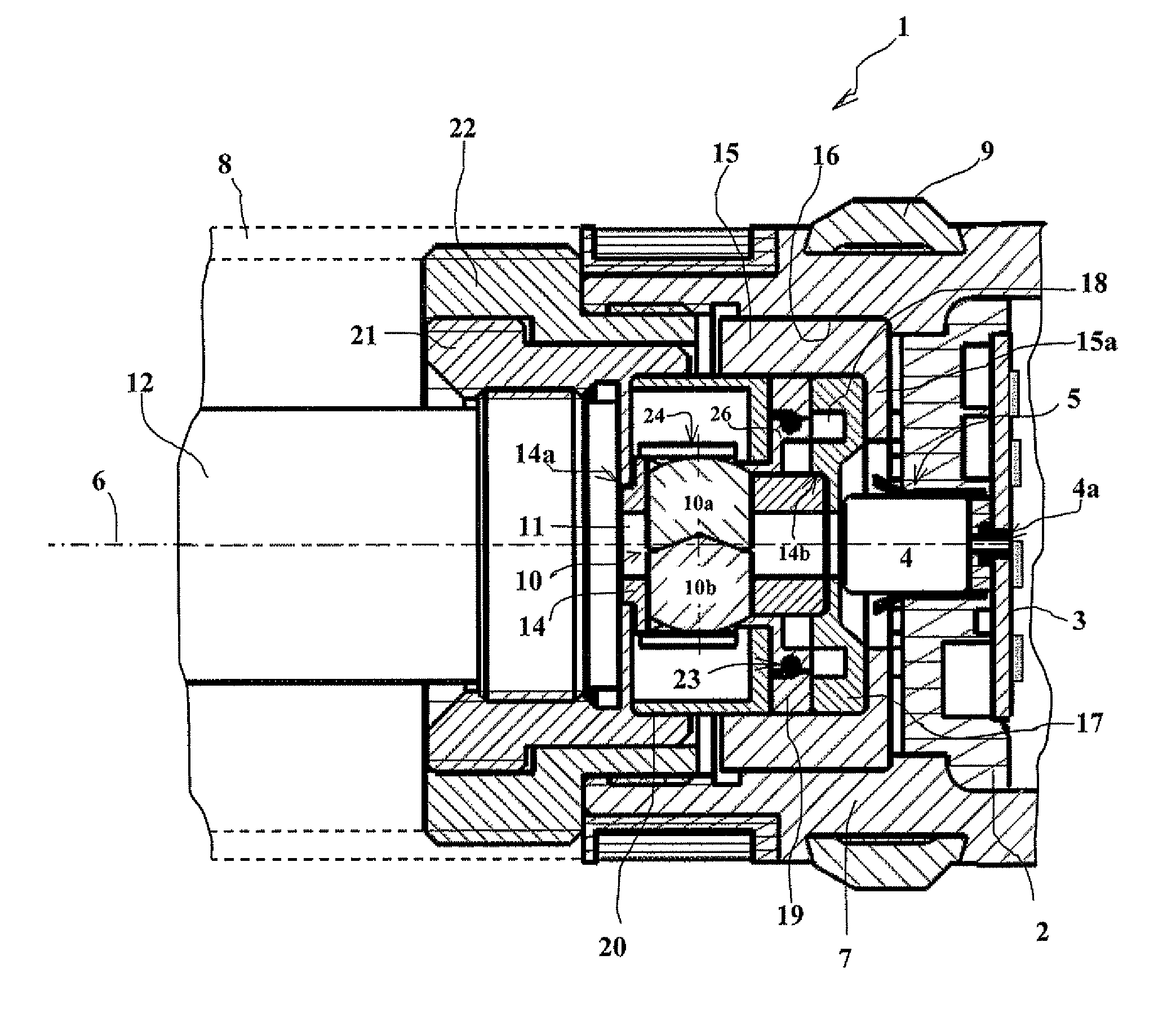
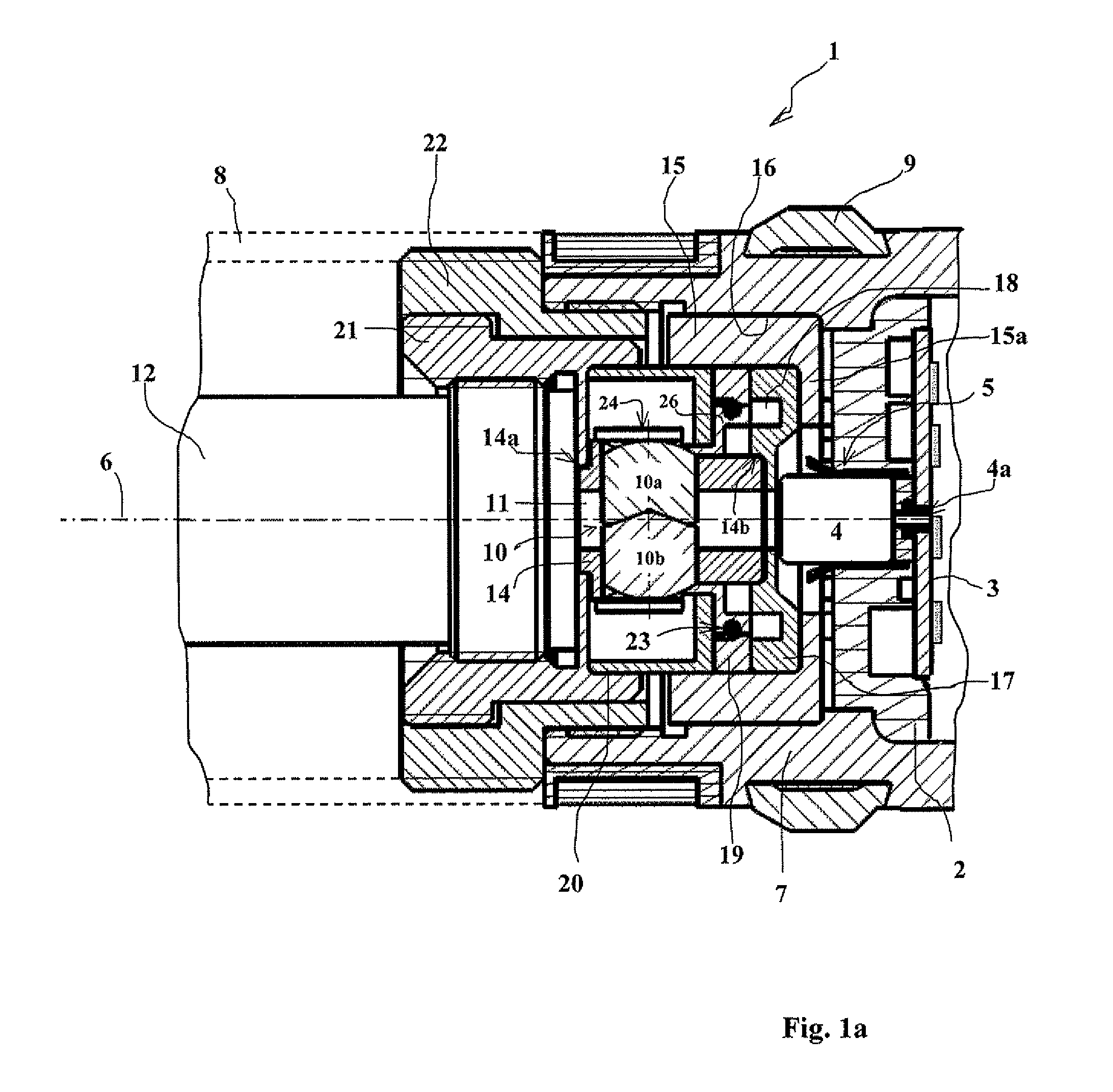
[0026]With reference to FIG. 1, a priming device (fuse) 1 according to the invention incorporates a firing module 2 that incorporates an electronic card 3 on which a detonator 4 is fixed.

[0027]The detonator 4 is electrically initiated. It incorporates an axial pin 4a that is directly connected to the electronic card 3. Furthermore, the electronic card 3 carries a conductive cup 5 (welded to the card) that surrounds the detonator 4 at least partially and ensures another electrical contact between the card 3 and the detonator 4.

[0028]The detonator 4 is thus fixed here, arranged along the axis 6 of the projectile and connected to the electronic card 3 of the firing module 2.

[0029]This results in a simplified mechanical module of this pyrotechnic element.

[0030]The electronic module 2 is arranged in a base 7 that closes the rear of the projectile and it is fixed to its body 8. The full projectile is not shown in the Figures. Part of its external profile is shown in dashes 8.

[0031]The bas...


PUM


Abstract

A safety and arming device for a spin-stabilized explosive projectile, said device incorporating a screen obstructing a transmission channel linking a detonator and a pyrotechnic relay, said screen comprising two half-screens able to move with respect to one another and transversally with respect to said channel, said two half-screens obstructing said channel when contacting one another, wherein said two half-screens are able to slide in a bore hole carried by a rotor coaxial to said projectile, said rotor is able to pivot on the axis of said projectile and carries said channel, said two half-screens locked into the position obstructing said channel by at least two locks, a first lock or inertial lock which retracts when said projectile is fired and a second lock or centrifugal lock formed by a spiral spring surrounding an external cylindrical surface of said rotor and applied against the ends of said half-screens.

Description

BACKGROUND OF THE INVENTION[0001]1. Field of the Invention[0002]The technical scope of the invention is that of priming devices (fuses) for spin-stabilized projectiles and in particular that of safety and arming devices equipping such priming devices.[0003]2. Description of the Related Art[0004]Spin-stabilized explosive projectiles, and in particular medium caliber projectiles (caliber of less than 50 mm), more often than not incorporate a safety and arming device that incorporates a rotor for the primer that is released further to the projectile being fired. This rotor has an out-of-balance that ensures the alignment of the primer with the rest of the pyrotechnic priming train.[0005]Patents FR-2689972 and FR-2533686 describe such safety and arming devices. The out-of-balance rotor is put into place in a cage that is free to rotate with respect to the projectile's axis.[0006]One drawback to these known devices lies in that they require a primer (thus a pyrotechnic component) to be p...

Claims


Application Information

Patent Timeline
Patent Type & Authority Patents(United States)
IPC IPC(8): F42C15/26
CPCF42C15/192F42C15/26F42C15/34
Inventor PADIOLLEAU, BERTRANDLAFONT, RENAUD
Owner NEXTER MUNITIONS
Features
  • Generate Ideas
  • Intellectual Property
  • Life Sciences
  • Materials
  • Tech Scout
  • Unparalleled Data Quality
  • Higher Quality Content
  • 60% Fewer Hallucinations
Learn More