
Endoluminal lining

Active Publication Date: 2012-10-09
ALLIUM
View PDF47 Cites 8 Cited by
  • Summary
  • Abstract
  • Description
  • Claims
  • Application Information

AI Technical Summary

Benefits of technology

[0013]The present invention provides an endoluminal device for insertion into a body lumen whose diameter changes dynamically over time. As explained above, such body lumens include a pulsating artery, a peristaltic organ, or a lumen adjacent to a sphincter. The device, referred to herein as a “lining”, is generally cylindrical in shape, and when positioned in the lumen, lines the lumen wall. In accordance with the invention, the lining is elastic and generally cylindrical in shape, having a cross-sectional area allowing it to conform to the cross-sectional shape of the lumen. Thus, for example, the lining may have a circular, triangular, or irregular cross-sectional shape, as required in any application. The lining has an unstrained caliber slightly larger than the maximal caliber of the body lumen in which it is to be deployed. The caliber of the lining decreases when radially inward forces are applied to the device as the lumen constricts. As described in detail below, the lining is structured so as to prevent it from collapsing when its caliber is decreased. Due to the elastic character of the lining, when the radial forces are removed, the lining returns to its unstrained caliber. Therefore, when the device of the invention is inserted into the body lumen, the device continuously conforms to the shape of the lumen as the caliber of the lumen fluctuates dynamically over time. The surface of the lining may be continuous, for example, either by embedding the elastic elements of the lining in a flexible material or covering the elastic elements in a flexible cylindrical sheath.
[0014]The lining of the invention may be used in conjunction with a stent. For example, use of lining of the invention adjacent to a stent eliminates the sharp pressure gradient that otherwise exists on the lumen wall around the ends of the stent. A region of a steep pressure gradient is known to induce ingrowth of tissue at the ends of the stent that partially or completely occludes the lumen at the ends of the stent.
[0015]The lining of the invention may be positioned in a lumen adjacent to a sphincter. Adjacent to the lining, a stent may be positioned in the lumen, so that the lining is flanked on one side by the sphincter and the other side by the stent. The lining and the stent may be fabricated as a single unit or may be formed as two separate units that are joined together before insertion into the lumen and inserted together as a single integral unit, or the lining and stent may be inserted separately. The stent maintains the patency of the lumen in a region that is separated from the sphincter by the lining. When the sphincter contracts, and the diameter of the lumen adjacent to the sphincter decreases, the diameter of the lining also decreases while conforming to the shape of the lumen wall. When the sphincter relaxes, and the diameter of lumen adjacent to the sphincter increases, the diameter of the lining also increases while conforming to the shape of the lumen wall. The lining thus dynamically conforms to the lumen shape adjacent to the sphincter during opening and closing of the sphincter.
[0016]Use of the lining in conjunction with a stent in a lumen adjacent to a sphincter has several advantages. First, it allows the stent to be more accurately positioned in a lumen near a sphincter. The distance between the sphincter and a region of the lumen in need of a stent is measured, and a lining in accordance with the invention is used having a length equal to this distance. The stent and the lining are then positioned as explained above. The presence of the lining near the sphincter also provides some support to the lumen wall adjacent to the sphincter without interfering with the functioning of the sphincter.
[0017]When a stent, or a graft containing a stent, is to be inserted into a pulsating artery such as the aorta, the graft or stent is used in conjunction with one or two linings of the invention. The stent or graft is positioned in the artery flanked by a lining of the invention at either one or both ends. The lining or linings expand during the increase in the caliber of the artery that occurs during systole, and contract during the decrease in the caliber of the artery that occurs during diastole. By dynamically conforming to the caliber of the vessel wall, flow of fluid between the stent or graft and the vessel wall is prevented.

Problems solved by technology

Placing a cylindrical stent in a body lumen adjacent to a sphincter often interferes with the proper functioning of the sphincter.
Inaccurate graft sizing and the inability of a graft to dynamically adjust to changes in the aorta's diameter during systole and diastole can result in the passage of fluid in the aneurysm between the vessel wall and the graft (endo-leaks), which can result in aneurysm expansion and rupture.

Method used


Image

  • Endoluminal lining
  • Endoluminal lining
  • Endoluminal lining

Examples


Embodiment Construction

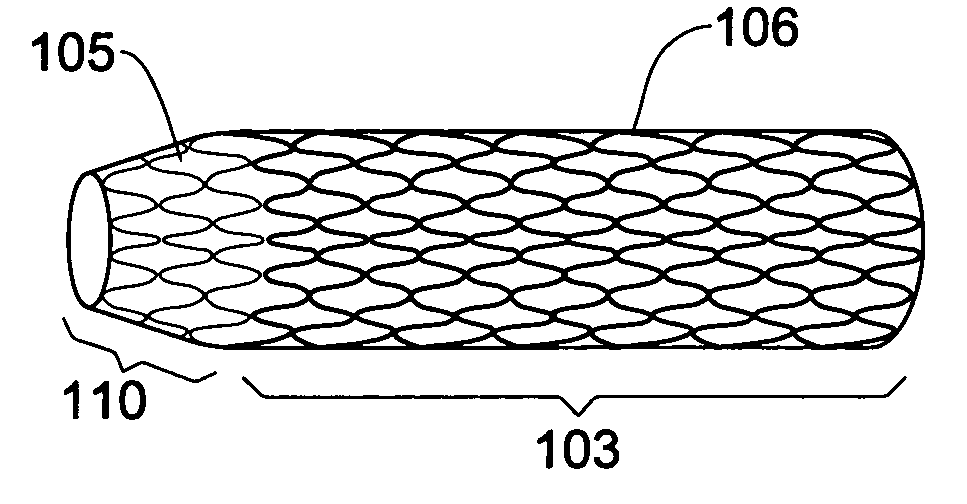
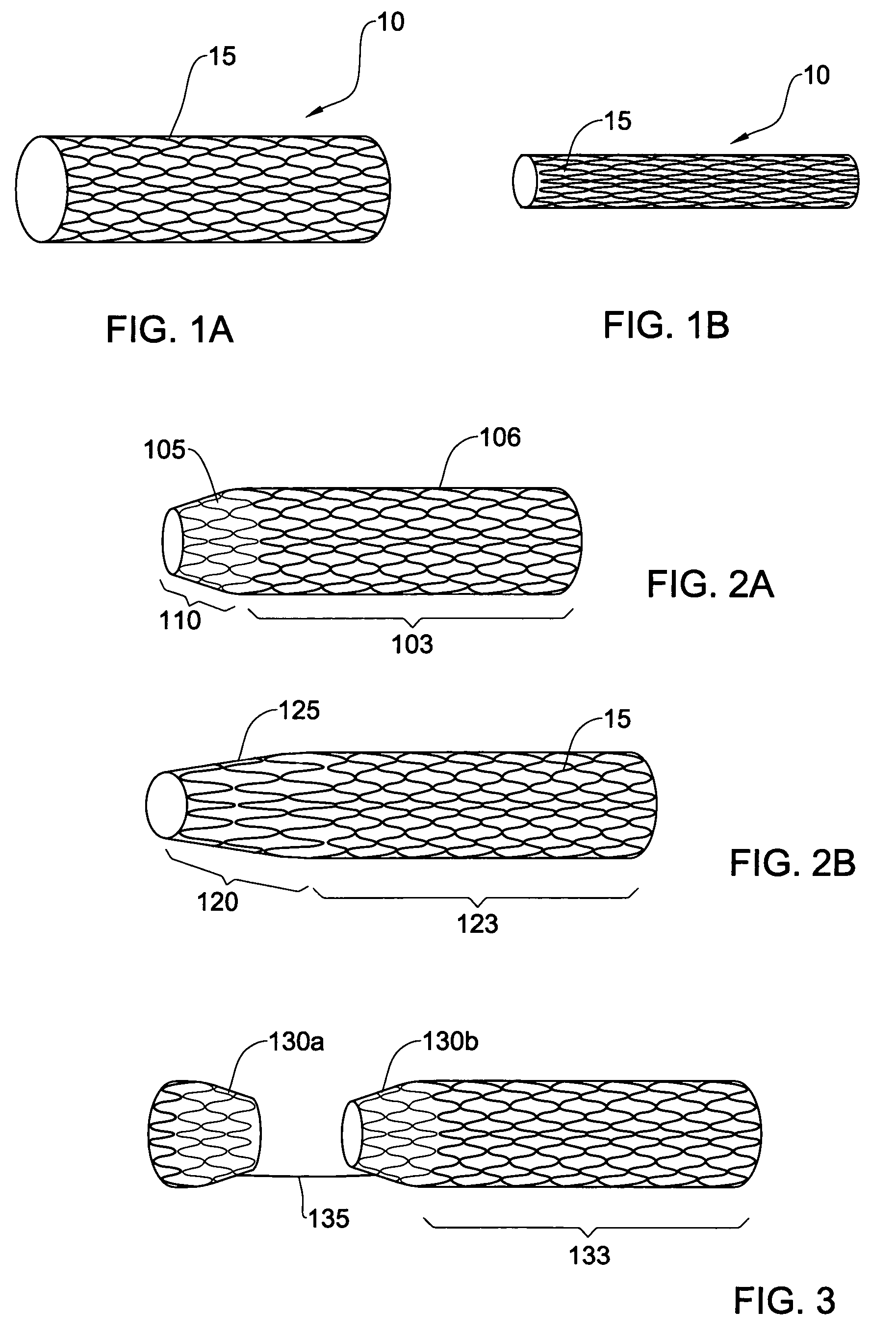
[0029]FIG. 1a shows a lining in accordance with one embodiment of the invention. The lining, generally indicated by 10, is formed from a resilient filament 15 that has been fashioned into an undulating helix. The filament may be made of spring steel, a super-elastic shape memory alloy such as Nitinol, or a shape memory alloy. The lining is shown in FIG. 1a in its unstrained conformation. When a radially inward force is applied to the lining 10, the lining 10 constricts while maintaining its generally cylindrical shape, as shown in FIG. 1b. As the lining 10 constricts, the surface density of the filament 15 in the wall of the lining 10 increases. Due to the resilient nature of the filament 15, when the radially inward forces are removed from the lining, the lining returns from the small caliber configuration shown in FIG. 1b to its large, unstrained caliber shown in FIG. 1a.

[0030]The lining 10 is dimensioned so as to have an unstrained large caliber that is slightly larger than the ...


PUM


Abstract

A cylindrical lining for insertion into a body lumen having a fluctuating caliber, such as a pulsating artery, peristaltic organ, or a lumen adjacent to a sphincter. The lining has a radial resistance less than a radial force applied to it by the lumen as the caliber of the lumen fluctuates so as to allow the lining to continuously conform to the shape of the lumen.

Description

FIELD OF THE INVENTION[0001]This invention relates to medical devices for insertion into body cavities.BACKGROUND OF THE INVENTION[0002]Stents are endoluminal devices that are inserted into body lumens and expanded in order to maintain the patency of the lumen. It is known for example, to use a stent to maintain the patency of an artery, a urethra, or a gastrointestinal organ.[0003]A stent is essentially a cylindrical device that can exist in two conformations. In the small caliber conformation, the stent is inserted into the body and delivered to the lumen to be treated. Once correctly positioned in the lumen, the stent is deployed by being brought into a large caliber in which it applies radially outward forces against the inner wall of the lumen. The stent is constructed so as to be able to withstand all radially inward forces applied to it by the lumen wall, so that the caliber of the stent does not change after deployment in the lumen.[0004]A stent may be formed, for example, f...

Claims


Application Information

Patent Timeline
IPC IPC(8): A61F2/82
CPCA61F2/82A61F2002/072
Inventor YACHIA, DANIELLEVY, RONNIE
Owner ALLIUM
Features
  • Generate Ideas
  • Intellectual Property
  • Life Sciences
  • Materials
  • Tech Scout
  • Unparalleled Data Quality
  • Higher Quality Content
  • 60% Fewer Hallucinations
Learn More