Conductor insertion plug

a technology of insertion plugs and conductors, applied in the direction of coupling device connections, contact members penetrating/cutting insulation/cable strands, instruments, etc., can solve the problems of poor electrical values and cannot be used universally, and achieve the effect of reducing operating forces, facilitating penetration, and facilitating penetration

Inactive Publication Date: 2013-08-20
WAGO VERW GMBH
View PDF9 Cites 14 Cited by
  • Summary
  • Abstract
  • Description
  • Claims
  • Application Information

AI Technical Summary

Benefits of technology

[0004]The object of the invention is to further develop a conductor insertion plug to the effect that it has, with the lowest possible operating forces, a broader range of use compared to the prior art and at the same time has the simplest and most compact structure possible.DISCLOSURE OF THE INVENTION
[0006]The design according to the invention makes it possible for a conductor insertion plug which is inserted into the conductor insertion opening to not be able to interengage with the clamping spring and accordingly to be able to be removed again with low operating forces. It is particularly advantageous here for that layer of the plug section which faces the clamping spring to consist of a steel alloy which is harder than or at least as hard as the clamping spring. As a result, the lowest possible tensile forces for removing the conductor insertion plug are ensured since the clamping edge of the clamping spring cannot interengage with the surface of the conductor insertion plug facing it and merely slides over the surface. At the same time, the plugging forces of the conductor insertion plug do not exceed the plugging forces for an electrical conductor and therefore there is no loss of convenience in this respect. In order to ensure as good a flow of current as possible from the busbar to the conductor insertion plug, that layer of the plug section which faces the busbar is in this case advantageously produced from a highly electrically conductive material, for example from copper or a copper alloy. This material of the second layer should, in this case, have a higher electrical conductivity than the material of the first layer which faces the clamping spring. In order to avoid an oxide layer which has negative influence on the electrical properties, the material of the second metal layer can be provided with a surface layer, for example a tin plating. As a result, the sliding properties of the second layer in relation to the busbar can also be improved.
[0008]The plug section is particularly advantageously substantially linear and / or has a substantially rectangular cross section over its section which can be inserted into the spring force terminal. As a result, the design of the plug section of the conductor insertion plug is kept particularly simple and compact and therefore also cost-effective.
[0010]In a further preferred embodiment (see FIG. 5), the conductor insertion plug can be in the form of a bridge with at least two plug sections which are arranged next to one another and extend in parallel in the same direction and are electrically conductively connected to one another. In this way, the bridge can be firmly clamped to the busbar and nevertheless be easily withdrawn again.

Problems solved by technology

One disadvantage of this is that the conductor insertion plug has to be matched to the clamping spring force connection and therefore cannot be used universally.
Since the conductor insertion plug makes contact only with the clamping spring which is produced from a relatively poorly conductive material, poor electrical values are also produced.

Method used


Image

  • Conductor insertion plug
  • Conductor insertion plug
  • Conductor insertion plug

Examples


Embodiment Construction

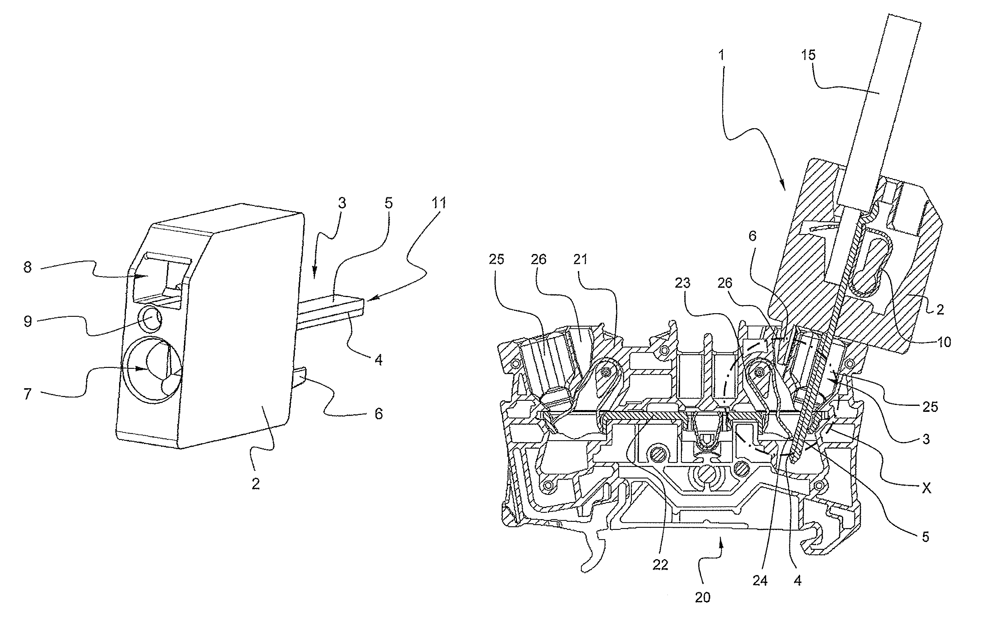
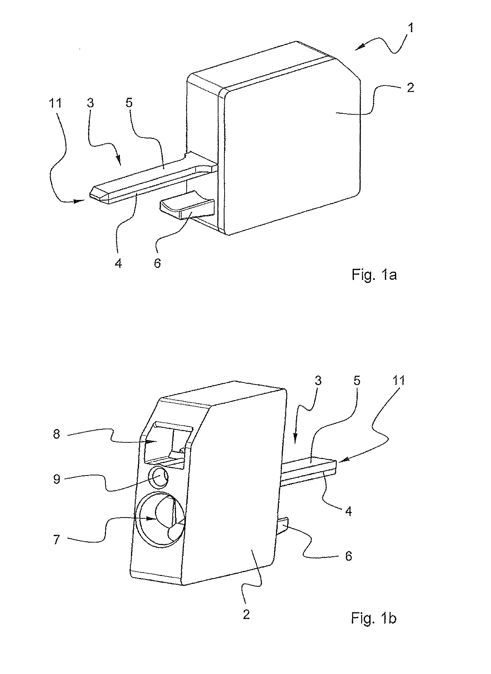
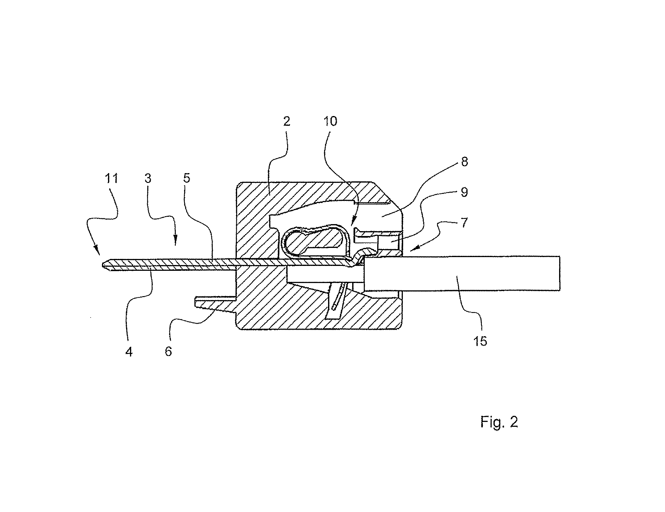
[0019]FIGS. 1a, 1b and 2 show an exemplary embodiment of a conductor insertion plug 1, with the conductor insertion plug 1 having a grip section 2 and a plug section 3. The plug section 3 has a first layer 4 which consists of a metal and a second metal layer 5 which preferably consists of copper or a copper alloy, with the second metal layer 5 extending into the insulating material housing 21 of the grip section 2 and there interacting in a known manner with a clamping spring 10 which, in this example, is in the form of a cage tension spring, in order to accommodate, in a clamped manner, an electrical conductor 15 (illustrated by way of example) which is inserted into a conductor insertion opening 7 in the grip section 2. Furthermore, the grip section 2 has an operating opening 8 for inserting a release tool (not illustrated) and a test opening 9 for inserting a test pin (likewise not illustrated). The internal design of the grip section 2 is merely exemplary, and therefore the grip...


PUM


Abstract

Conductor insertion plug (1) having a grip section (2) and at least one conductive plug section (3) for insertion into a conductor insertion opening (25) in a spring force terminal (20) which has an insulating material housing (21) with at least one busbar (22) inserted therein and at least one clamping spring (23), with the clamping spring (23) having a clamping edge (24) which is oriented at an acute angle in relation to an electrical conductor which is inserted into the conductor insertion opening (25) and, together with an opposite section of the busbar (22), forms a clamping point for the electrical conductor, with the plug section (3) which is located outside the grip section (2) being formed, at least in a contact region which is intended to make contact with the clamping spring (23), with at least two layers comprising a first layer (4) which faces the clamping spring (23) and is composed of a first metal material and a second layer (5) which faces the busbar (22) and is composed of a second metal material.

Description

[0001]The invention relates to a conductor insertion plug having a grip section and at least one conductive plug section for insertion into a conductor insertion opening in a spring force terminal which has an insulating material housing with at least one busbar inserted therein and at least one clamping spring, with the clamping spring having a clamping edge which is oriented at an acute angle in relation to an electrical conductor which is inserted into the conductor insertion opening and, together with an opposite section of the busbar, forms a clamping point for the electrical conductor.PRIOR ART[0002]DE 10 2008 055 776.5 (not yet published) describes a conductor insertion plug which can be inserted into a conductor insertion opening in a spring force terminal and which is held in a clamped manner in the clamping position of the spring force connection by a clamping spring. To this end, the tip of the conductor insertion plug is shaped in such a way that it latches behind an edg...

Claims


Application Information

Patent Timeline
Patent Type & Authority Patents(United States)
IPC IPC(8): H01R11/20
CPCH01R4/4818H01R4/4845H01R9/2491G01R1/0408H01R4/48455H01R4/48185
Inventor GASSAUER, STEPHAN
Owner WAGO VERW GMBH
Why Eureka
Try Eureka