Surgical clip applier with high torque jaws

a high-torque, clip-like technology, applied in the field of surgical clip-like appliers, can solve the problems of greater trauma inflicted on the patient's body, and achieve the effect of maintaining or reducing the loss of co-planarity

Inactive Publication Date: 2013-08-20
TYCO HEALTHCARE GRP LP
View PDF103 Cites 147 Cited by
  • Summary
  • Abstract
  • Description
  • Claims
  • Application Information

AI Technical Summary

Benefits of technology

[0028]In a further aspect of the present disclosure, a jaw blade for use in a surgical clip applier, including a first leg, a second leg spaced from and parallel to the first leg, the first and second legs defining a plane, each leg including a jaw integrally formed at a distal end thereof, and at least one inter-leg engaging member extending between the first and the second legs and operatively engaged therewith, wherein the inter-leg engaging member maintains or reduces the loss of co-planarity of the first leg with respect to the second leg. It is envisioned that the the operative engagement of at least one inter-leg engaging member causes the first and second leg members to deflect and maintain their co-planarity when one of the first and second legs is deflected in a direction which is orthogonal with respect to the plane defined by the first and second legs.
[0035]Another object of the present disclosure is to provide an apparatus for applying surgical fasteners or clips which has increased resistance to the loading (e.g., torsional, twisting, bending, etc.) effects experienced during grasping, manipulating and blunt dissecting techniques.
[0037]A further object of the present disclosure is to provide a surgical fastener or clip applier that is easier to load with a fastener or clip and which makes forming the same easier.
[0039]A further object of the invention is to provide a surgical fastener or clip applier that has increased resistance to torsional forces and properly loads, forms and applies surgical fasteners or clips after having performed a blunt dissection procedure.

Problems solved by technology

Undoubtably, the more incisions required, the greater the trauma inflicted on the patient's body.

Method used


Image

  • Surgical clip applier with high torque jaws
  • Surgical clip applier with high torque jaws
  • Surgical clip applier with high torque jaws

Examples


Embodiment Construction

[0052]Preferred embodiments of the presently disclosed endoscopic applier having high torque jaws will now be described in detail with reference to the drawing figures wherein like reference numerals identify similar or identical elements. In the drawings and in the description which follows, the term “proximal”, as is traditional will refer to the end of the surgical applier which is closest to the operator, while the term “distal” will refer to the end of the applier which is furthest from the operator.

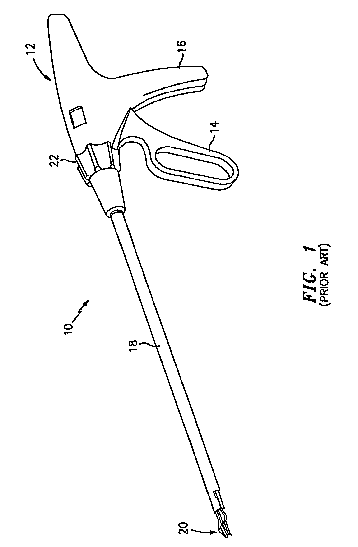
[0053]Referring now in detail to the figures, in which like reference numerals identify similar or identical elements, FIG. 1 illustrates a typical prior art surgical fastener or clip applying apparatus, here shown as surgical clip applier 10. Clip applier 10 includes a handle portion 12 having a movable handle 14 and a stationary hand grip 16, which handle portion 12 serves to operate a jaw mechanism 20 through the provision of an elongated body portion 18. For example only, the ju...


PUM


Abstract

Jaw blades for use in surgical clip appliers are disclosed. The jaw blades include a first leg and a second leg, each leg having a jaw integrally connected thereto and at least one inter-leg engaging member that extends from one of the first and second legs and is engageable with the other of the first and second legs. When the at least one inter-leg engaging member is engaged with the other of the first and second legs, a displacement in a first direction of one of the first and second legs causes a first corresponding displacement in the first direction of the other of the first and second legs, and such that a displacement in a second direction, opposite the first direction, of the one of the first and second legs causes a second corresponding displacement in the second direction of the other of the first and second legs.

Description

CROSS-REFERENCE TO RELATED APPLICATIONS[0001]This application is a National Stage Application of PCT / US03 / 10231 filed on Apr. 3, 2003 under 35 USC §371 (a), which claims priority of U.S. Provisional Patent Application Ser. No. 60 / 371,652 filed Apr. 10, 2002, the disclosures of each of the above-identified applications are hereby incorporated by reference in their entirety.BACKGROUND[0002]1. Technical Field[0003]The present disclosure relates to an apparatus for applying surgical clips to body tissue during open, laparoscopic or endoscopic procedures and, more particularly, to a surgical clip applier having jaws configured and adapted to withstand torsional forces acting thereon.[0004]2. Background of Related Art[0005]In laparoscopic and endoscopic surgical procedures, a small incision is made in the patient's body to provide access for a cannula device. Once extended into the patient's body, the cannula provides an access port which allows insertion of various surgical instruments, ...

Claims


Application Information

Patent Timeline
Patent Type & Authority Patents(United States)
IPC IPC(8): A61B17/10A61B17/128A61B17/32A61B17/12
CPCA61B17/1285A61B2017/320044
Inventor VIOLA, FRANK J.
Owner TYCO HEALTHCARE GRP LP
Why Eureka
Try Eureka