
Portable terminal with rotating display

a technology of rotating display and portability, applied in the direction of electrical apparatus construction details, instruments, electrical apparatus casings/cabinets/drawers, etc., to achieve the effect of convenient viewing angl

Inactive Publication Date: 2013-08-20
SNAPTRACK
View PDF6 Cites 0 Cited by
  • Summary
  • Abstract
  • Description
  • Claims
  • Application Information

AI Technical Summary

Benefits of technology

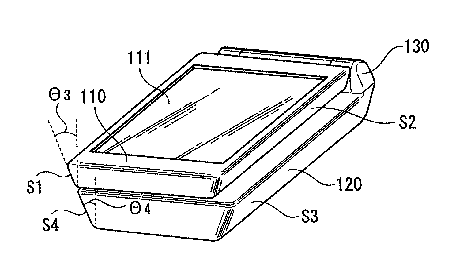
The present invention provides a portable terminal that can be placed on a desktop at an easily viewable angle and in a stable manner when watching television broadcasts. The terminal has a folded display unit that is directed outward, allowing for convenient viewing.

Problems solved by technology

However, when the user watches the broadcasts with the portable telephone terminal by placing the terminal on a desk, or the like, the user may have to lay the terminal parallel with a locating plane or raise the terminal perpendicular to the locating plane.

Method used


Image

  • Portable terminal with rotating display
  • Portable terminal with rotating display
  • Portable terminal with rotating display

Examples


Embodiment Construction

[0023]An embodiment of the present invention will be described below with reference to FIGS. 1 to 9.

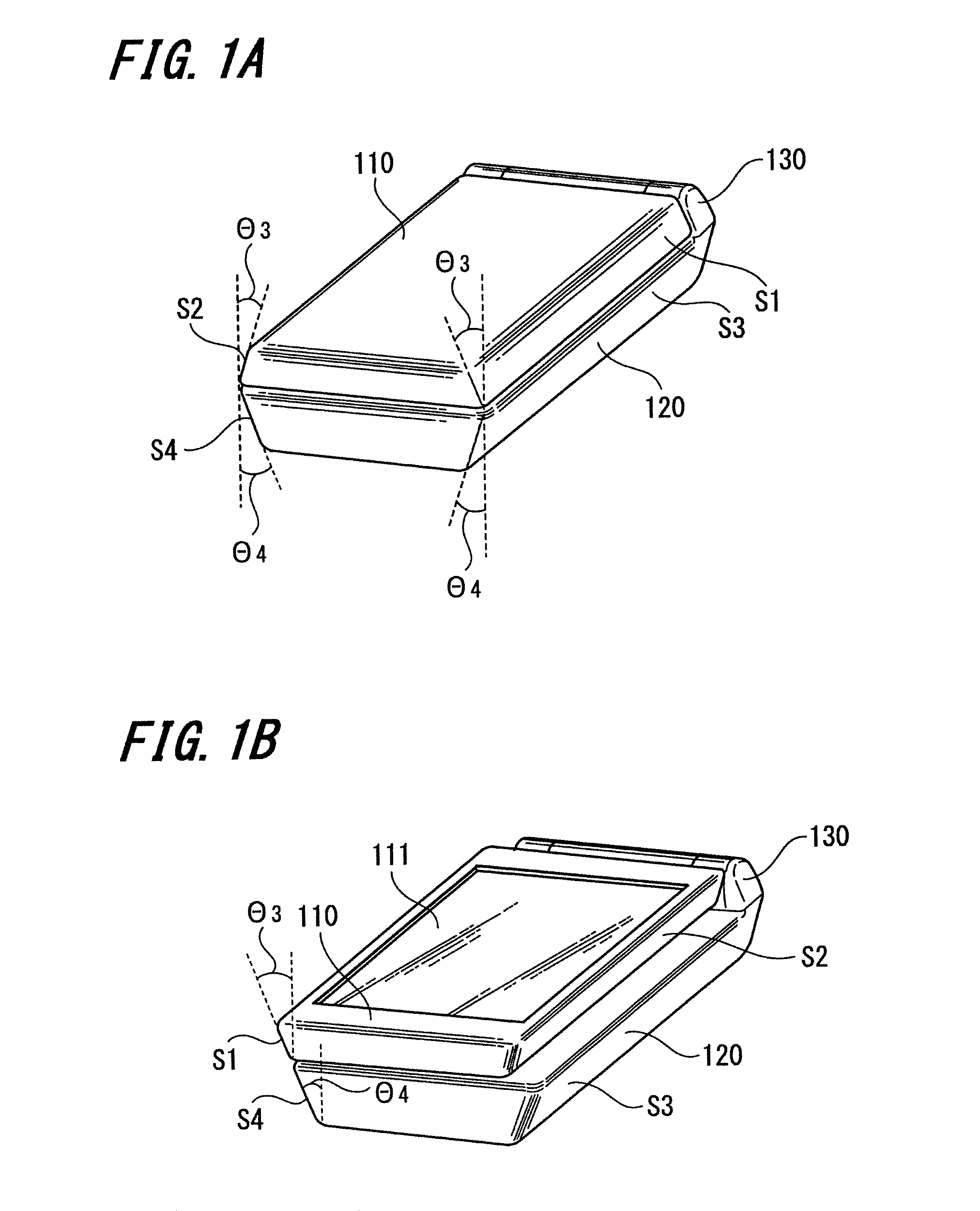
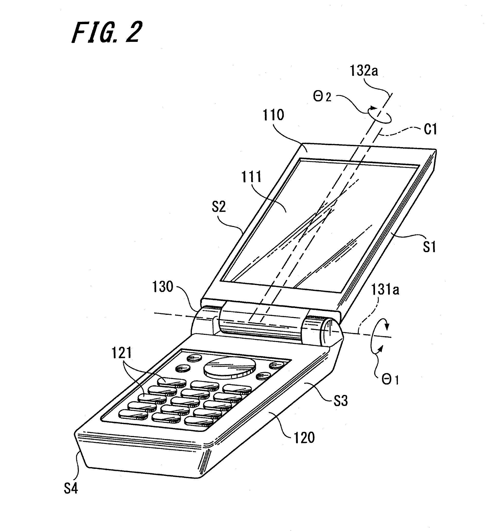
[0024]In the present embodiment, a portable telephone terminal has a function to receive television broadcasts. First, a whole configuration of the portable telephone terminal of the present embodiment will be described with reference to FIGS. 1 to 3. The portable telephone terminal 100 of the present embodiment shown in FIGS. 1 to 3 is formed as a foldable portable telephone terminal. FIG. 1 shows a closed state, FIG. 2 shows an open state, and FIG. 3 shows a rotation state of an enclosure.

[0025]The portable telephone terminal 100 in an open state described with reference to FIG. 2 has a first enclosure 110 and a second enclosure 120 each having an elongated shape and rotatably connected to each other via a hinge 130. The hinge 130 is a biaxial hinge having a first rotation axis 131a around which the first enclosure 110 and the second enclosure 120 may be rotated in a rotational dire...


PUM


Abstract

Disclosed is a portable terminal including a first enclosure having a display unit; a second enclosure having an operation unit; a first connection unit foldably connecting the first enclosure to the second enclosure by being rotated around a first center axis; and a second connection unit connecting the first enclosure to the second enclosure and allowing the first enclosure to be rotated between a first position and a second position and around a second center axis perpendicular to the first center axis, the second center axis located in a position shifted by a predetermined amount from a center of the first enclosure. The first enclosure is displaced from the second enclosure corresponding to the second center axis when the enclosures are folded via the first connection unit in a state where the first enclosure is rotated to the second position in the second connection unit.

Description

CROSS REFERENCES TO RELATED APPLICATIONS[0001]The present invention contains subject matter related to Japanese Patent Application JP 2006-241885 filed in the Japanese Patent Office on Sep. 6, 2006, the entire contents of which being incorporated herein by reference.BACKGROUND OF THE INVENTION[0002]1. Field of the Invention[0003]The present invention relates to a portable terminal suitably used as a portable telephone terminal, for example. More particularly, the present invention relates to a portable terminal used as a portable telephone terminal having two enclosures connected to each other via a mechanism called a biaxial hinge.[0004]2. Description of the Related Art[0005]In recent years, there have been an increased number of portable telephone terminals that include a first enclosure having an operation unit and a second enclosure having a display unit, both of which are foldably connected via a biaxial hinge with two rotation axes located perpendicular to each other. Further,...

Claims


Application Information

Patent Timeline
Patent Type & Authority Patents(United States)
IPC IPC(8): H04M1/00H04M1/02H04W88/02
CPCH04M1/0212H04M1/0235H04B1/38
Inventor MASUDA, TAKEFUMI
Owner SNAPTRACK
Learn More