Device stand

a technology for devices and stands, applied in the direction of machine supports, furniture parts, electric apparatus casings/cabinets/drawers, etc., can solve the problem of no useful stand with a compact capacity

Active Publication Date: 2010-12-07
POWER SUPPORT
View PDF23 Cites 23 Cited by
  • Summary
  • Abstract
  • Description
  • Claims
  • Application Information

AI Technical Summary

Benefits of technology

[0006]An object of this invention is to provide the stand for the electronic device with the capacity to hole the headset in a handy manner. This device should conveniently hold the electronic device in an easily viewable angle and also is capable of holding the headset cord in a handy manner while transporting the electronic device.
[0007]To achieve this purpose, this invention provides the stand for the electronic device with the capacity to hold the headset, comprising a main body capable of holding cords, an attaching section positioned on the main body for an electronic device to be mounted and secured thereon, a stand cover capable of temporary fitting over the main body and having a section for preventing the cords from unraveling, and a connecting section which joints the main body and the stand cover and allows the stand cover to spread apart from the main body with the hinge section as the fulcrum.
[0009]As complying with the structure described in detail below, the headset cords can be conveniently wound around the electronic device to adjust a length of the headset cables and securely held thereat around a desirable position, and at the same time the electronic device sits on a slope of the stand with a desirable angle to provide the best screen view of the device. No complex and bulky structure for winding or retracting the cords of the headset is necessary, thereby lightening the device with the winding or retracting component. The present invention also provides a preventive measure for tangling of cords and also for having lengthily cords.

Problems solved by technology

Therefore, there is no useful stand with a capacity of compactly holding the headset in a handy manner.

Method used


Image

  • Device stand
  • Device stand
  • Device stand

Examples


Embodiment Construction

[0016]Next, a preferred embodiment of this invention will be explained with reference to the accompanied drawings.

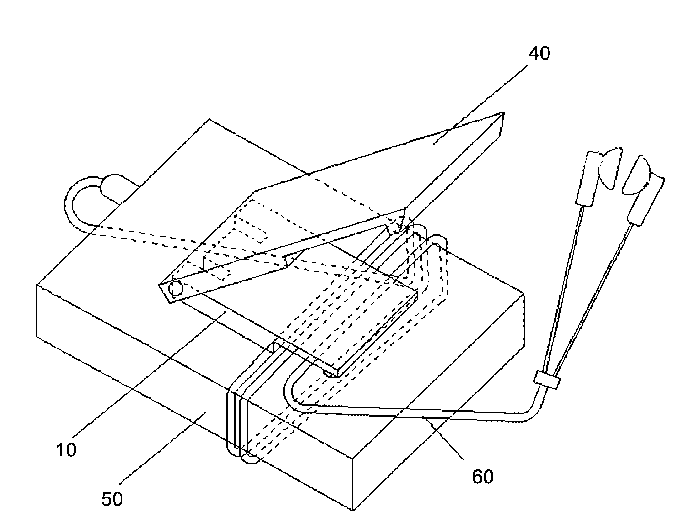
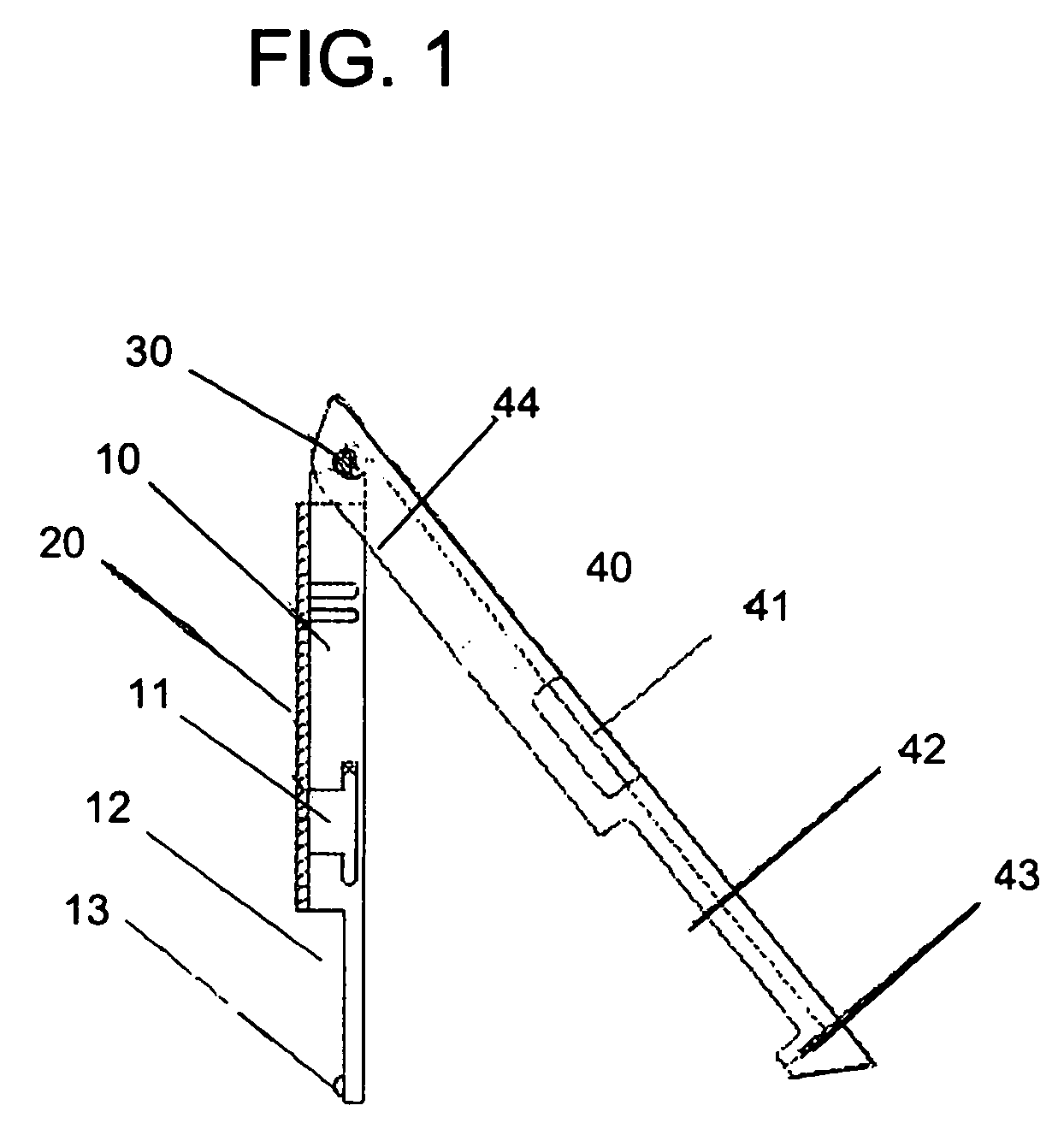
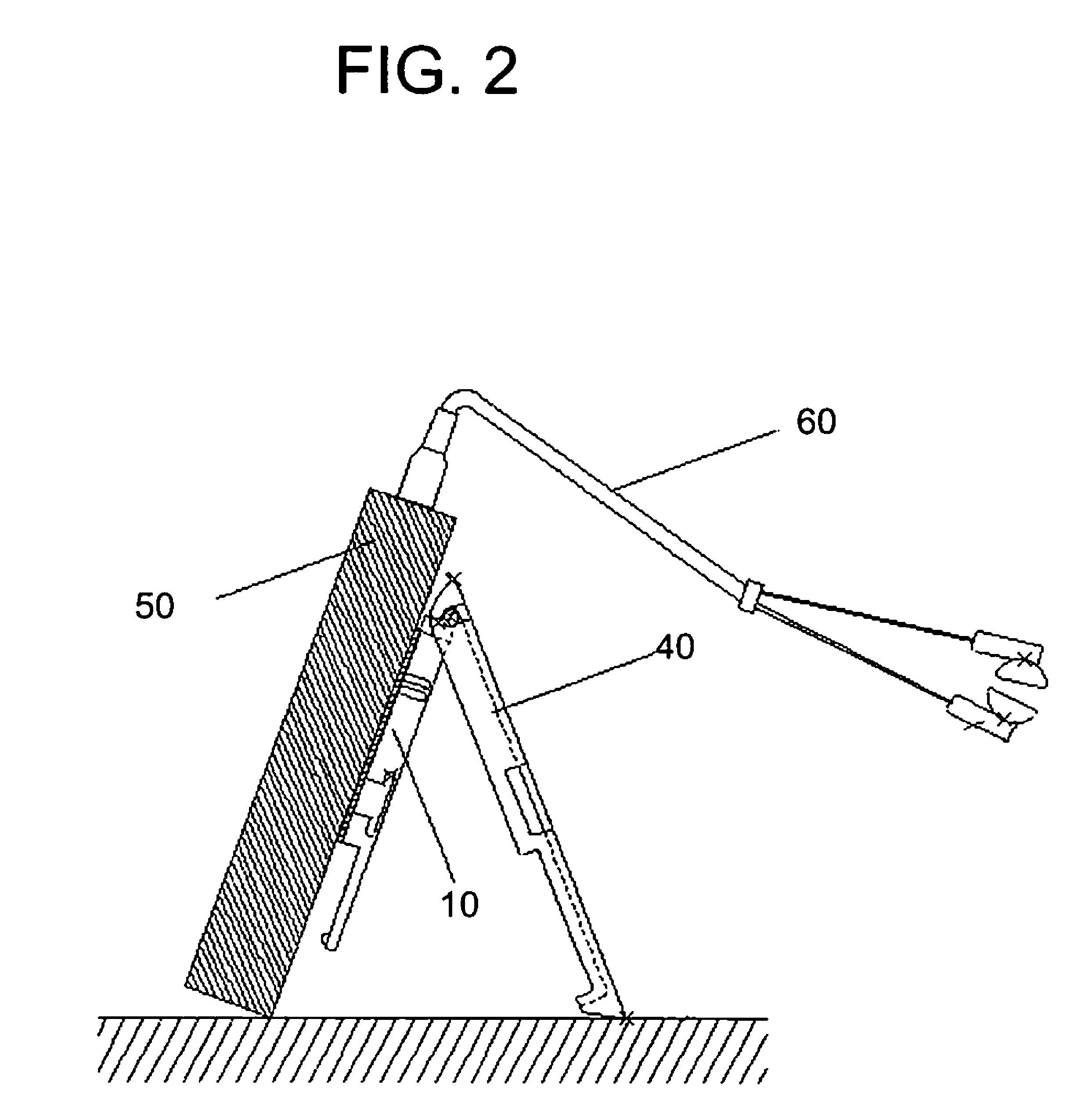
[0017]The embodiment is explained with reference to FIGS. 1-6. FIG. 1 is a side view of the present invention. The electronic device stand 1 mainly comprised of a main body 10, an adhesive section 20, a hinge section 30, and a stand cover 40.

[0018]The main body 10 is a shallow rectangular box and is mainly comprised of a hook groove 11, a cord holder 12, and a cord holding protuberance 13. The hook groove 11 is located at an intermediate portion of the man body 10. The cord holder 12 is located below the hook groove 11. The cord holding protuberance 13 is located at one end of the main body 10. An adhesive section 20 is provided on a surface of the main body 10 facing the electronic device 50.

[0019]The stand cover 40 is a flat panel, the other end thereof is pivotally connected to the other end of the main body 10 via a hinge section 30, so that the stand cover 40 moves ...


PUM


Abstract

This invention is to provide the stand for the electronic device with the capacity to hole the headset in a handy manner. The stand comprises the main body capable of holding cords, the attaching section positioned on the main body for the electronic device to be mounted and secured thereon, stand cover capable of temporary fitting over the main body and having the section for preventing the cords from unraveling, and the connecting section which joints the main body and the stand cover and allows the stand cover to spread apart from the main body with the hinge section as the fulcrum.

Description

BACKGROUND OF THE INVENTION[0001]1. Field of the Invention[0002]This invention relates a stand for a various devices, more particularly a stand for electronic devices with a headset cord receiver.[0003]2. Description of the Related Arts[0004]Conventionally, a stand for the electronic device and a cord receiving equipment are two independent units and are separately sold in the market. A typical conventional stand comprised of two flat panels pivotally connected and hinged at one end lines thereof. When a consumer uses the stand, the other end lines thereof spread apart from each other with one end lines thereof as a fulcrum, and the other end lines which are opened to sit on a table to make a triangle side view. An example of modifications to the conventional stand described above is U.S. Pat. No. 4,044,980. Generally, an adhesive material is applied on one surface of one of the flat panel on which the electronic device is placed and affixed. As in U.S. Pat. No. 6,370,401 B1, a head...

Claims


Application Information

Patent Timeline
Patent Type & Authority Patents(United States)
IPC IPC(8): A47G1/24
CPCH05K5/0204
Inventor MASE, RYOICHI
Owner POWER SUPPORT
Why Eureka
Try Eureka