Handle for a hand-held power tool

a technology of hand-held power tools and handles, which is applied in the direction of portable power-driven tools, percussive tools, drilling machines, etc., can solve the problems of difficult actuator actuation and the ergonomically most unfavorable hand of the operator, and achieve the effect of convenient holding

Active Publication Date: 2006-08-29
HILTI AG
View PDF12 Cites 15 Cited by
  • Summary
  • Abstract
  • Description
  • Claims
  • Application Information

AI Technical Summary

Benefits of technology

[0009]These and other objects of the present invention, which will become apparent hereinafter, are achieved by providing a handle that has a forwardly inclined position in which the handle, starting from the spindle axis, i.e., in the direction of its longitudinal extent, is inclined, at least for the most part, relative to the spindle axis, in the operational direction of the tool. Thereby, a hand of an operator occupies an ergonomically favorable position in applications, such as working the corner region between a wall and a floor, when the handle is pivoted by 180° with respect to the normal position of the handle during a conventional wall operation of the tool. The power tool is held so that the spindle axis lies beneath the handle and in a position in which it is closest to the small finger of the operator hand holding the handle. With this position, the spindle axis is located closely to the floor or bottom, and the handle is conveniently held by the operator. The convenient holding is achieved as a result of the forearm axis of the operator and the spindle axis of the tool extending parallel to each other when the tool is pivoted about the spindle axis by 180° with respect to its normal position.
[0010]In accordance with a preferred embodiment of the present invention, the handle is pivotable between its forwardly inclined position and its normally inclined position in which the handle starting from the spindle axis, is inclined, at least for the most part, in a direction opposite the operational direction of the tool. This permits to use the tool in any desirable application, for normal operation on walls, floors, and ceilings and for operation in corner regions, in particular between a wall and a floor. In this way, the operator's hand always occupies an ergonomically optimal position in each possible application.
[0011]Advantageously, the balancing axis of the handle forms an angle in a range from 10° to 40°, in particular, an angle of 30°, between the forwardly inclined position and the normally inclined position of the handle. The balancing axis is an axis that passes through the centers of cross-sectional surfaces of the handle at opposite ends of the finger seat. Pivoting of the balancing axis in the range from 10° to 40° insures obtaining an ergonomically optimal holding of the tool handle in both pivotal positions of the handle. The angle of 30° proved to be particularly advantageous as it insures an ergonomically favorable aligning of the handle in both pivotal positions.

Problems solved by technology

A drawback of the known switch handle consists in that with, e.g., working a wall in the vicinity of a floor, in particular, during mounting of skirting boards, the hand of an operator grips the handle in the ergonomically most unfavorable position.
Moreover, in such cases, the actuation of the actuator is rather difficult as the actuator is not located any more in the region of the fore-and middle fingers but rather in the region of the small-and ring fingers.

Method used


Image

  • Handle for a hand-held power tool
  • Handle for a hand-held power tool
  • Handle for a hand-held power tool

Examples


Embodiment Construction

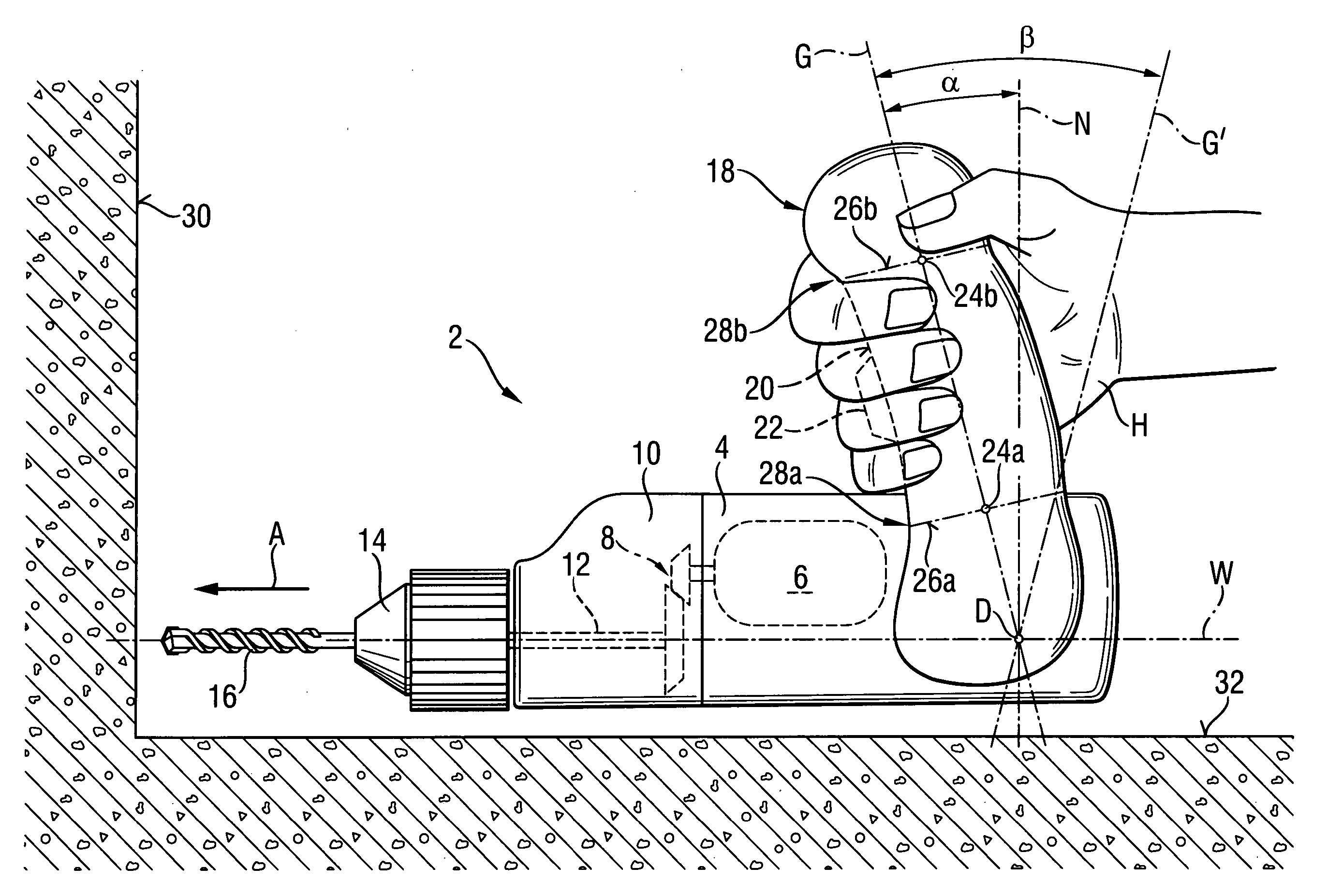
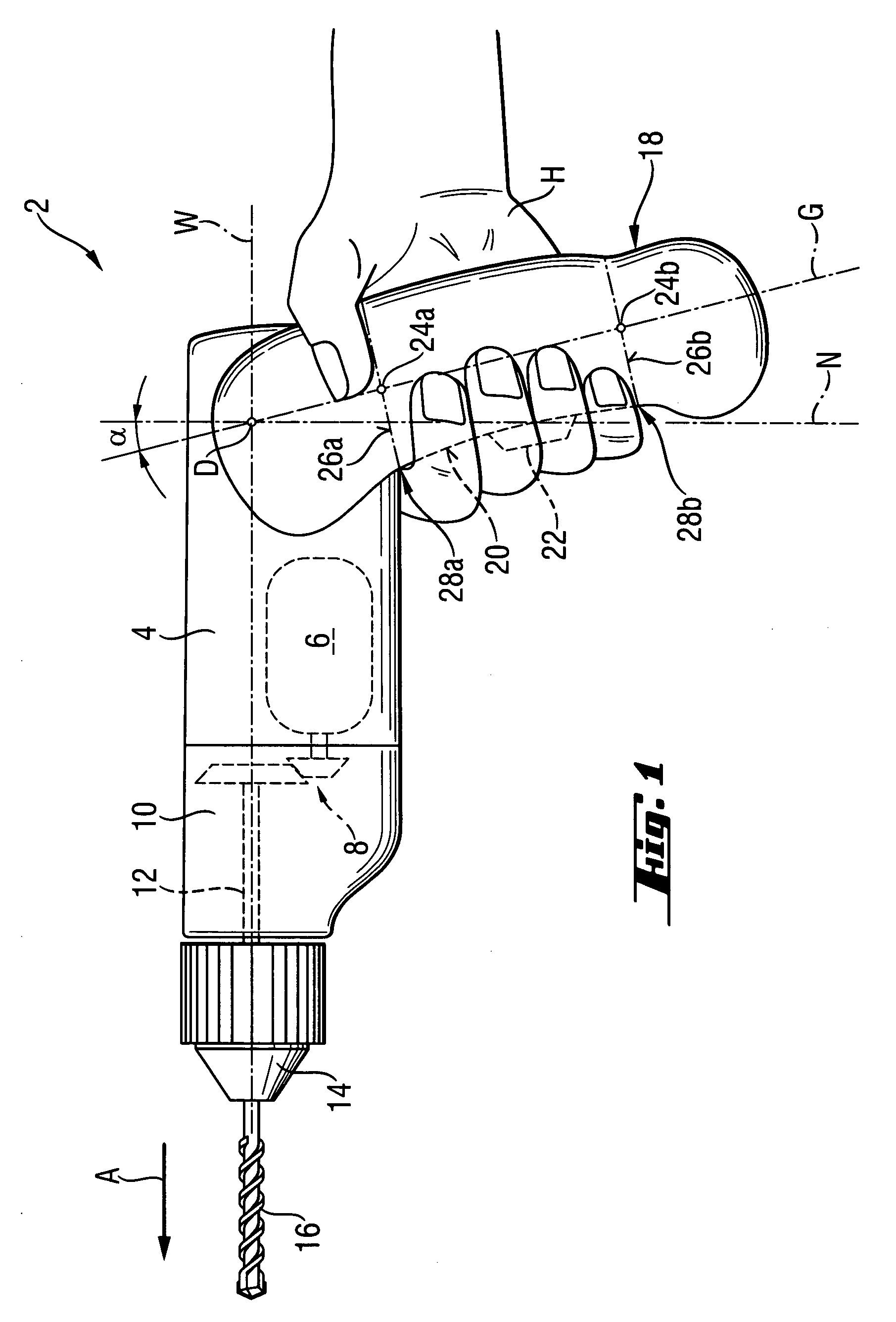
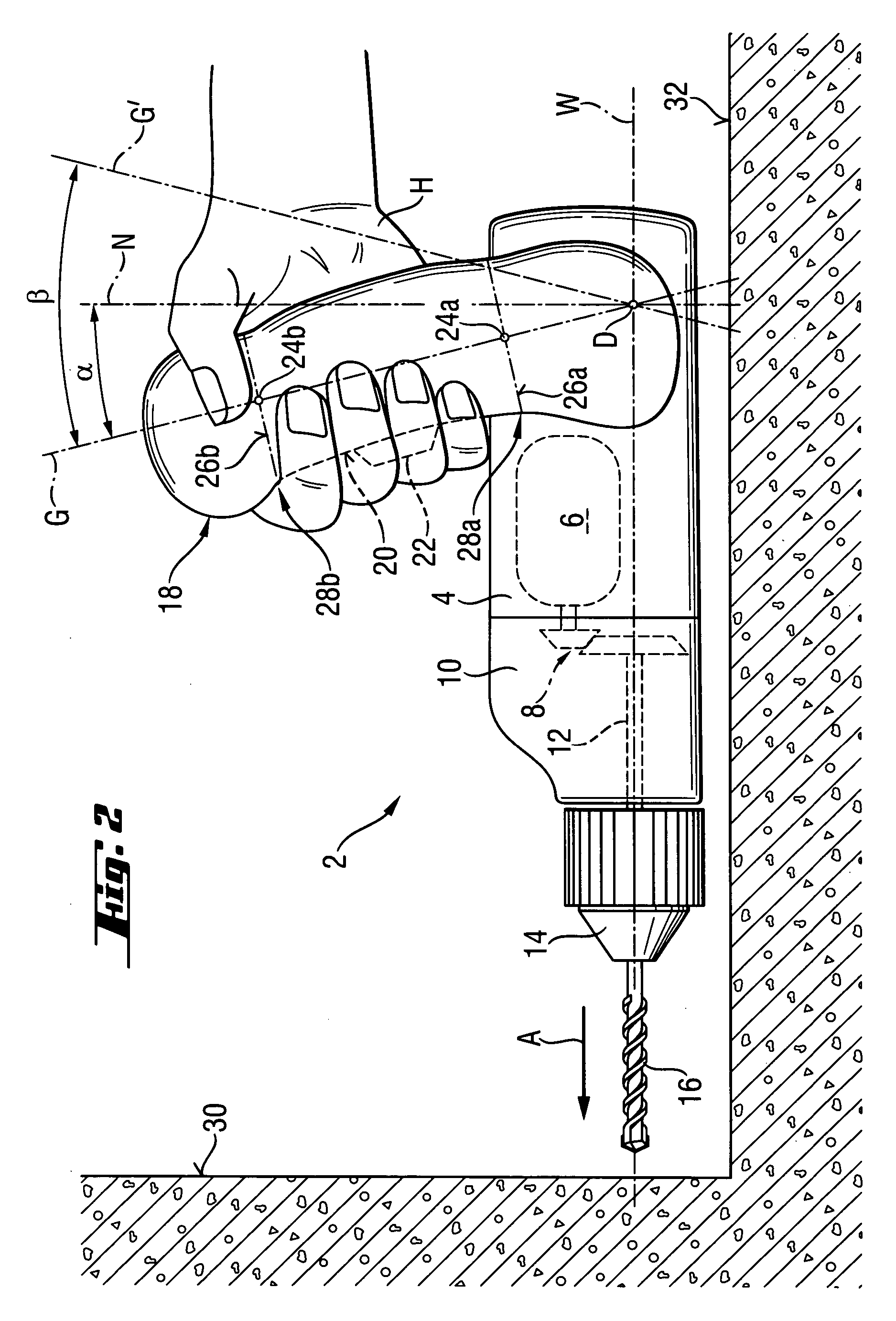
[0029]A power hand-held tool 2, which is shown in FIG. 1, has a combined drilling and screw-driving function and includes essentially a motor unit 4 with a motor 6 shown with dash lines. A schematically shown gear unit 10 with a gear transmission 8 connects the motor 6 with a tool spindle 12 likewise shown with dash lines. At the front, facing in the operational direction A of the power tool 2, end of the spindle 12, there is provided a chuck 14 in which a working tool 16 is received. The tool spindle 12 has a spindle axis W.

[0030]At the rear, with respect to the operational direction A, end of the motor unit 4, there is provided a handle 18 having a shape of a pistol grip, i.e., it is provided with an ergonomically favorable curvature. The handle 18 is held with a human hand H, with the small, ring, middle, and forefinger engaging or gripping a finger seat 20. The finger seat 20 is provided on a side of the handle 18 facing in the operational direction A and is formed by a bottom o...


PUM

PropertyMeasurementUnit
angleaaaaaaaaaa
angleaaaaaaaaaa
angleaaaaaaaaaa

Abstract

A hand-held power tool including a tool spindle (12) having a motor (6) for driving the tool spindle (12), a handle (18) having a forwardly inclined position in which the handle (18), starting from the spindle axis (W) is inclined, at least for a most part, in an operational direction (A) of the power tool (2), and an actuator (22) provided on the handle (18) for switching the motor (6) on and off.

Description

BACKGROUND OF THE INVENTION[0001]1. Field of the Invention[0002]The present invention relates to hand-held power tools such as, e.g., motor-driven screw-driving, drilling, and chisel tools, in particular to drills, hammer drills, rotary-percussion tools, battery-driven screw-driving tools having each a handle, in particular, a pistol grip-shaped handle having an ergonomical curvature and inclined over its longitudinal extent, for the most or completely, with respect to the spindle axis of the power tool, with an actuator for switching the motor on and off being mounted on the handle.[0003]2. Description of the Prior Art[0004]Handles, which are inclined relative to the spindle axis, proved themselves over the years as optimal handles for motor-driven hand-held tools. Mostly, the handles have a shape of a pistol grip. The later has a curvature adapted to a human hand. Such handles can constitute a component of all possible handle shapes such as spade handles, T-handles, or be provided...

Claims


Application Information

Patent Timeline
Patent Type & Authority Patents(United States)
IPC IPC(8): E21B3/00B23B45/00B25C1/00B25D17/04B25F5/02
CPCB25F5/02Y10T408/96
Inventor OBERMEIER, JOSEFHOFBRUCKER, THOMAS
Owner HILTI AG
Why Eureka
Try Eureka