Stapler device and method

a staple gun and device technology, applied in the field of stapling devices and methods, can solve the problems of affecting the operation of the staple gun, the user may not be able to generate enough force to activate the staple gun, and the stapler handle may need to be depressed

Active Publication Date: 2007-11-08
FPC CORP
View PDF9 Cites 15 Cited by
  • Summary
  • Abstract
  • Description
  • Claims
  • Application Information

AI Technical Summary

Benefits of technology

[0017] Typically, the stapling method may be used to allow the stapler to be loaded with a force while the stapler device is held by the user at a convenient position, such as at belt height or when placed on a surface to gain leverage. The stapler can then be moved to a second location, such as an overhead or other awkward position before r...

Problems solved by technology

One drawback results when using a staple gun to attach an article to a surface that is overhead or otherwise hard to reach.
When the user's hand is at an awkward position or angle, the user may be unable to generate enough force to activate the staple gun.
Moreover, even if the user can generate the required force while in the awkward position, if a number of staples are required, fatigue may quickly be experienced.
To accomplish the task, a large number of staples are needed to be applied at vari...

Method used


Image

  • Stapler device and method
  • Stapler device and method
  • Stapler device and method

Examples


Embodiment Construction

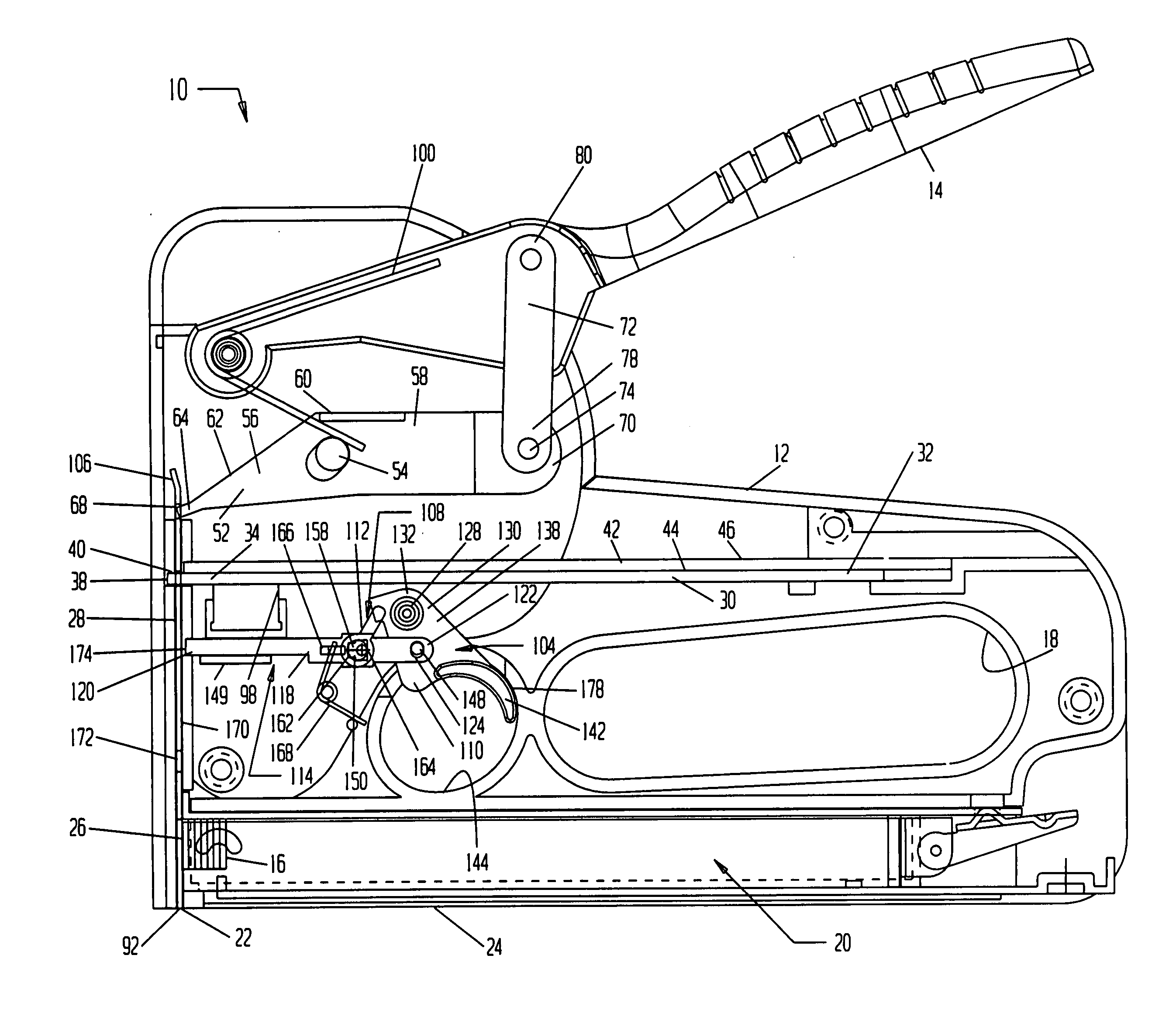
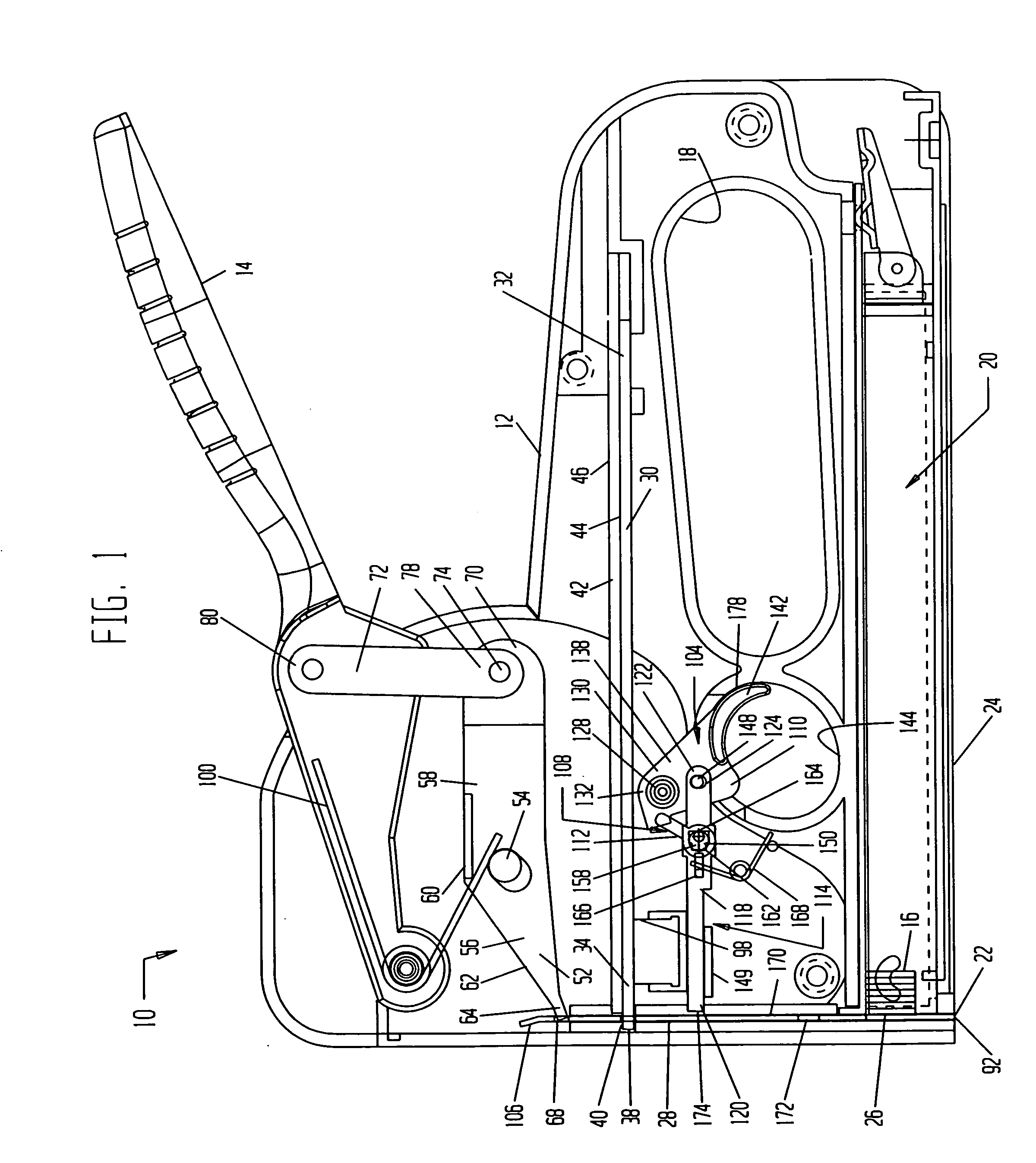
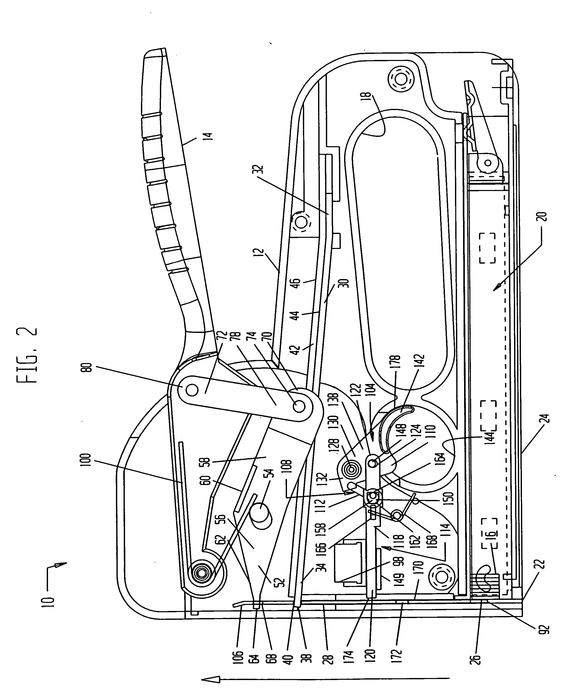
[0038]FIG. 1 shows a stapler device 10 that has a housing 12 with an attached handle 14 and a grip 18. Housing 12 may be of a multiple section construction, with the sections assembled together to form housing 12. Positioned adjacent the bottom 24 of housing 12 is a staple feed mechanism 20, for advancing the staples 16 stored on a staple magazine toward an opening 22 in the housing bottom 24. A striker 28, shown also in FIG. 12, is slideably mounted within housing 12 for reciprocal upward and downward movement. In the operation of stapler device 10, striker 28 sequentially and forcefully moves the lead staple 26 of the magazine downward. Lead staple 26 is expelled out opening 22 to drive staple 26 through an article and into an adjacent surface.

[0039] A spring 30, for applying a stapling force to striker 28, has a rear end 32, and a front end 34 with a front tip 38 extending therefrom. Spring 30 is mounted within housing 12 with a generally perpendicular orientation to striker 28,...


PUM

PropertyMeasurementUnit
Forceaaaaaaaaaa

Abstract

A stapler device and a method of stapling an article. The stapler has a striker and a spring for driving the striker to apply a staple. During the stapling cycle, the striker and spring are cocked and loaded prior to being release to apply the staple. While the stapler is in the cocked and loaded position the stapling cycle is automatically interrupted to maintain the spring and the striker in the cocked and loaded position. The stapler device may be then moved to a second location before the interruption is discontinued by an actuator. Once the stapling cycle is continued, the cocked and loaded striker and spring are released to apply a staple. The device is also selectively capable of a second mode of operation wherein the stapling cycle is not interrupted.

Description

FIELD OF THE INVENTION [0001] The present invention relates to a device and method for stapling. More particularly the present invention relates to improvements to a staple gun. BACKGROUND OF THE INVENTION [0002] Conventional spring powered staple guns may be used to staple one or more articles to a surface. Typically, the article to be stapled is manually aligned and temporarily held in place against the surface it is to be stapled to. The staple gun is then positioned at the desired location for application of a staple. The handle of the staple gun is forced downward by the user to cause the staple gun to shoot a staple out of the gun. The staple is thereby forced through the article and into the surface to attach the article to the surface. [0003] Conventional staple guns have certain drawbacks when used for a number of types of applications. One drawback results when using a staple gun to attach an article to a surface that is overhead or otherwise hard to reach. In such instanc...

Claims


Application Information

Patent Timeline
IPC IPC(8): B25C5/06
CPCB25C5/10Y10T29/49947Y10T29/5343Y10T29/49954
Inventor KAMINS, MICHAELFURUSHO, MELVIN
Owner FPC CORP
Why Eureka
Try Eureka