Card connector

a card connector and card technology, applied in the direction of coupling device connection, engagement/disengagement of coupling parts, instruments, etc., can solve the problem that the micro sim card is often not located in the correct position of the receiving chamber to electrically connect with the corresponding electrical terminal, and achieves accurate electrical connection, smooth insertion, and smooth insertion.

Inactive Publication Date: 2013-08-27
PROCONN TECH CO LTD
View PDF7 Cites 10 Cited by
  • Summary
  • Abstract
  • Description
  • Claims
  • Application Information

AI Technical Summary

Benefits of technology

[0005]An object of the present invention is to provide a card connector, which is adapted for receiving a SIM card and a micro SIM card therein. The card connector includes an insulating housing of a substantially rectangular board shape with a receiving chamber opened along a front-to-rear direction in a top thereof and penetrating through a front side of the insulating housing. A pair of side walls forms at two opposite sides of the receiving chamber. A fool-proofing board is movably located in the receiving chamber, and a substantial middle of a front thereof is concaved rearward to form an inserting chamber. A pair of receiving fillisters is opened in two face-to-face inner sides of the side walls to connect with the receiving chamber and each extends along the front-to-rear direction in front of the fool-proofing board. A bottom side of the receiving chamber defines a plurality of terminal cavities. A plurality of electrical terminals is assembled in the terminal cavities of the insulating housing respectively and elastically stretches upward into the receiving chamber and the inserting chamber. Two restraining members each has a base strip disposed in a front of the corresponding receiving fillister of the insulating housing, and an elastic arm extending rearward from a rear end of the base strip and inclined inward to stretch into the receiving chamber. A shielding shell encloses the insulating housing together with the electrical terminals and the restraining members. In use, the elastic arms of the restraining members are pressed into the corresponding receiving fillisters when the SIM card is inserted in the receiving chamber to electrically contact with the electrical terminals. In the process of inserting the micro SIM card into the card connector, the elastic arms of the restraining members elastically resist against two opposite side edges of the micro SIM card so as to guide a rear of the micro SIM card to be smoothly inserted into the inserting chamber and further realize an electrical connection between the micro SIM card and the electrical terminals.
[0006]As described above, the card connector utilizes the elastic arms of the restraining members stretched in the receiving chamber, to elastically resist against the two opposite side edges of the micro SIM card and restrain the micro SIM card therebetween in the process of inserting the micro SIM card into the card connector, so as to ensure that the rear of the micro SIM card is smoothly inserted into the inserting chamber. So, an accurate electrical connection can be assured between the micro SIM card and the electrical terminals.

Problems solved by technology

As a result, the micro SIM card often fails to be located in the correct position of the receiving chamber to electrically connect with the corresponding electrical terminals.

Method used


Image

  • Card connector
  • Card connector
  • Card connector

Examples


Embodiment Construction

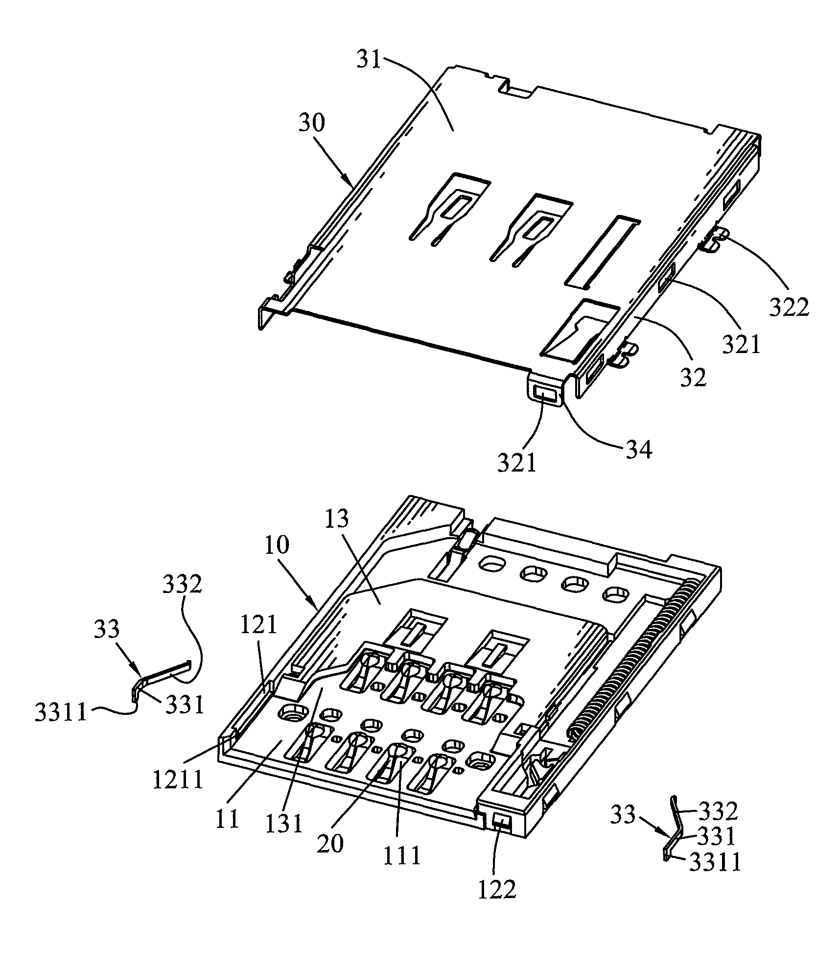
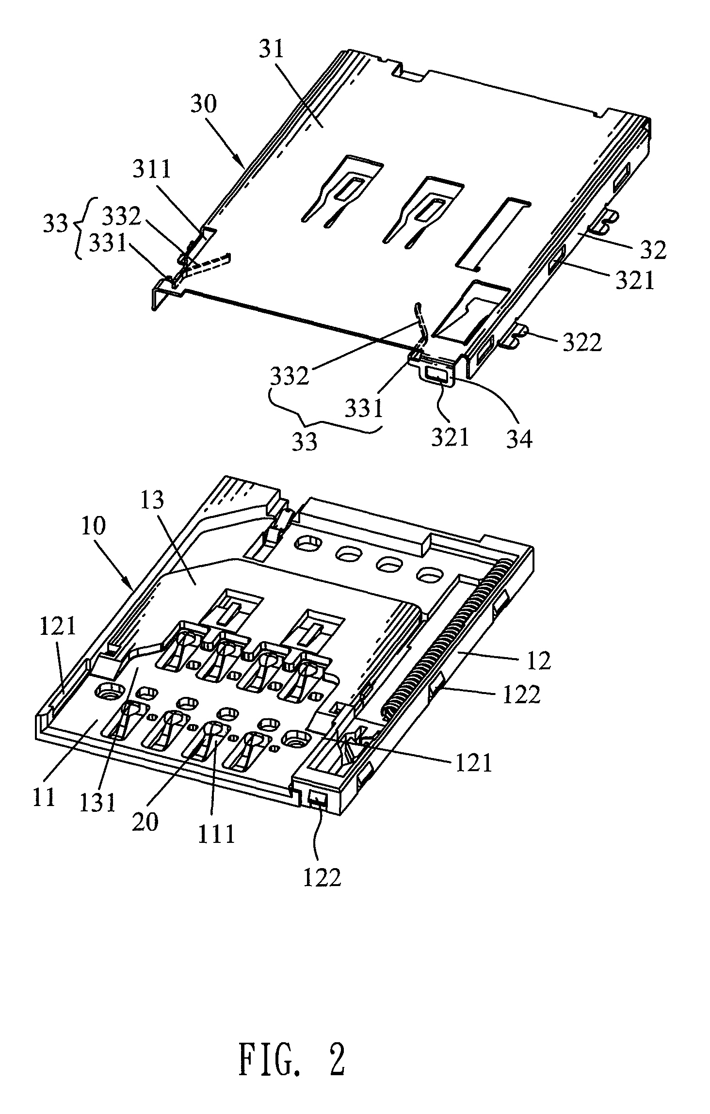
[0013]Referring to FIGS. 2-5, a card connector according to the present invention is adapted for receiving a SIM card 40 and a micro SIM card 50 therein. The card connector includes an insulating housing 10, a plurality of electrical terminals 20, two restraining members 33 and a shielding shell 30.

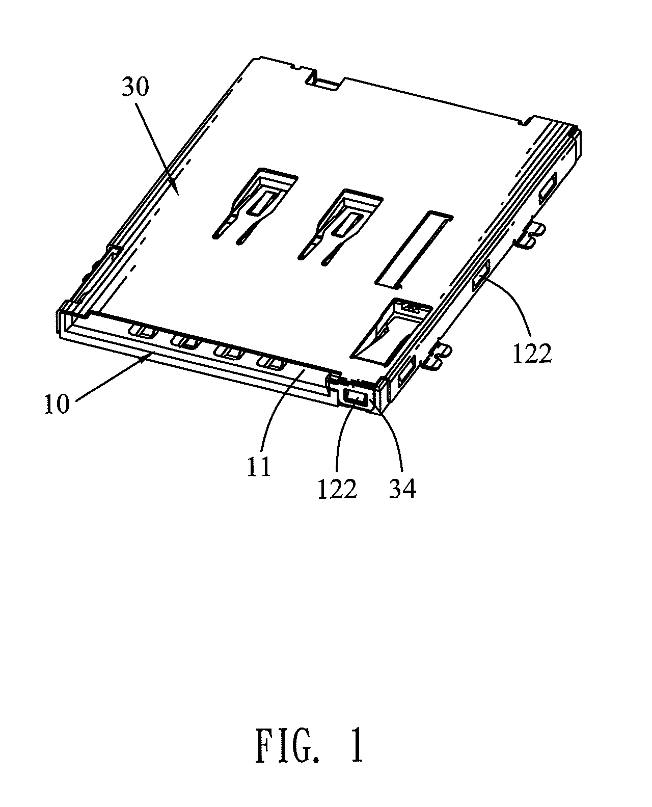
[0014]Referring to FIGS. 1-5, the insulating housing 10 is of a substantially rectangular board shape, and has a receiving chamber 11 opened along a front-to-rear direction in a top thereof and penetrating through a front side of the insulating housing 10. Accordingly, a pair of side walls 12 forms at two opposite sides of the receiving chamber 11. A fool-proofing board 13 is movably located in the receiving chamber 11, and a substantial middle of a front thereof is concaved rearward to form an inserting chamber 131. A pair of receiving fillisters 121 is opened in two face-to-face inner sides of the side walls 12 to connect with the receiving chamber 11 and each extends along the front-to...


PUM


Abstract

A card connector includes an insulating housing defining a receiving chamber and an inserting chamber connected with the receiving chamber, electrical terminals assembled in the insulating housing, and a shielding shell enclosing the insulating housing. Two receiving fillisters are opened in two inner sides of two side walls forming at two opposite sides of the receiving chamber. Two restraining members each has a base strip disposed in the receiving fillister, and an elastic arm inclined inward into the receiving chamber. The elastic arms are pressed into the receiving fillisters when a SIM card is inserted in the receiving chamber. In the process of inserting a micro SIM card into the card connector, the elastic arms resist against two opposite side edges of the micro SIM card to guide a rear of the micro SIM card to be smoothly inserted into the inserting chamber.

Description

BACKGROUND OF THE INVENTION[0001]1. Field of the Invention[0002]The present invention relates to a card connector, and more particularly to a card connector capable of inserting two kinds of different cards therein.[0003]2. The Related Art[0004]Traditionally, a card connector capable of receiving two kinds of different cards, such as a SIM card and a micro SIM card, includes an insulating housing, a plurality of electrical terminals assembled in the insulating housing and a shielding shell enclosing the insulating housing together with the electrical terminals. The insulating housing defines a receiving chamber for receiving the SIM card and the micro SIM card therein. However, the receiving chamber is often opened in accordance with the SIM card. So, only the SIM card can be exactly inserted in the receiving chamber of the card connector, but the micro SIM card has a smaller shape than the size of the receiving chamber. As a result, the micro SIM card often fails to be located in t...

Claims


Application Information

Patent Timeline
Patent Type & Authority Patents(United States)
IPC IPC(8): H01R24/00
CPCG06K7/0043H01R27/00
Inventor CHAN, CHING-JUNGYU, TA-CHIH
Owner PROCONN TECH CO LTD
Why Eureka
Try Eureka