Fiber-optic probe

a fiber-optic probe and optical fiber technology, applied in the field of fiber-optic probes, can solve the problem of low kink resistan

Inactive Publication Date: 2013-08-27
PULSION MEDICAL SYSTEMS SE
View PDF6 Cites 2 Cited by
  • Summary
  • Abstract
  • Description
  • Claims
  • Application Information

AI Technical Summary

Benefits of technology

[0011]According to one aspect of the present invention, this object is achieved by a fiber-optic probe for intravascular measurements comprising a fiber-optic core for conducting electro-magnetic radiation from a proximal end of said probe to a distal end of said probe and a sheath made of synthetic sheath material and disposed around said core. The fiber-optic probe comprises at least one reinforcing fiber made of material different from the material of which the fiber-optic core is made. This allows selecting the material of the reinforcing fiber focusing on mechanical properties thereof. In other words, optical and mechanical functions can be allocated to separate elements of the probe, thus adding a degree of freedom and facilitating optimization of the respective material properties.
[0032]It is to be noted that the above features of fixing the probe relative to the catheter in an irreversible manner, wherein preferably the forces exerted upon the fiber-optic probe are limited and preferably a predefined advancement of the probe is provided, may also be very advantageous in connection with conventional probes.

Problems solved by technology

On the other hand, a smaller probe diameter usually results in a lower kink resistance.

Method used


Image

  • Fiber-optic probe
  • Fiber-optic probe
  • Fiber-optic probe

Examples


Embodiment Construction

[0048]The conventional probe shown in FIG. 8 has a fiber-optical bundle constituting the fiber-optical core 1. The core comprises both efferent fibers for guiding light from a light source (not shown) to the distal tip of the probe and afferent fibers for guiding reflected, scattered or fluorescent light from the distal tip of the probe to detecting means (not shown) connected with the probe. The core 1 is protected by a sheath 2. Due to the rather large probe diameter, kinking resistance is acceptable.

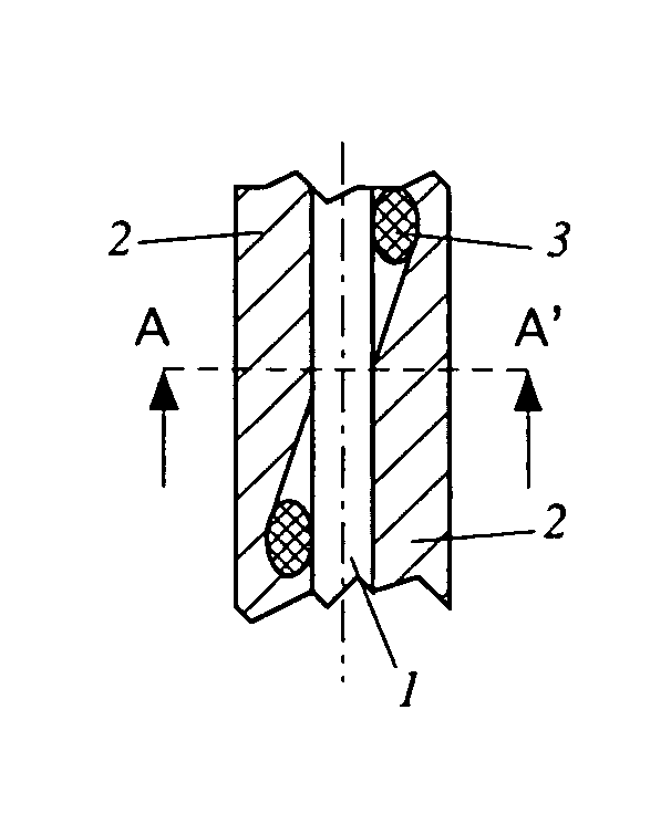
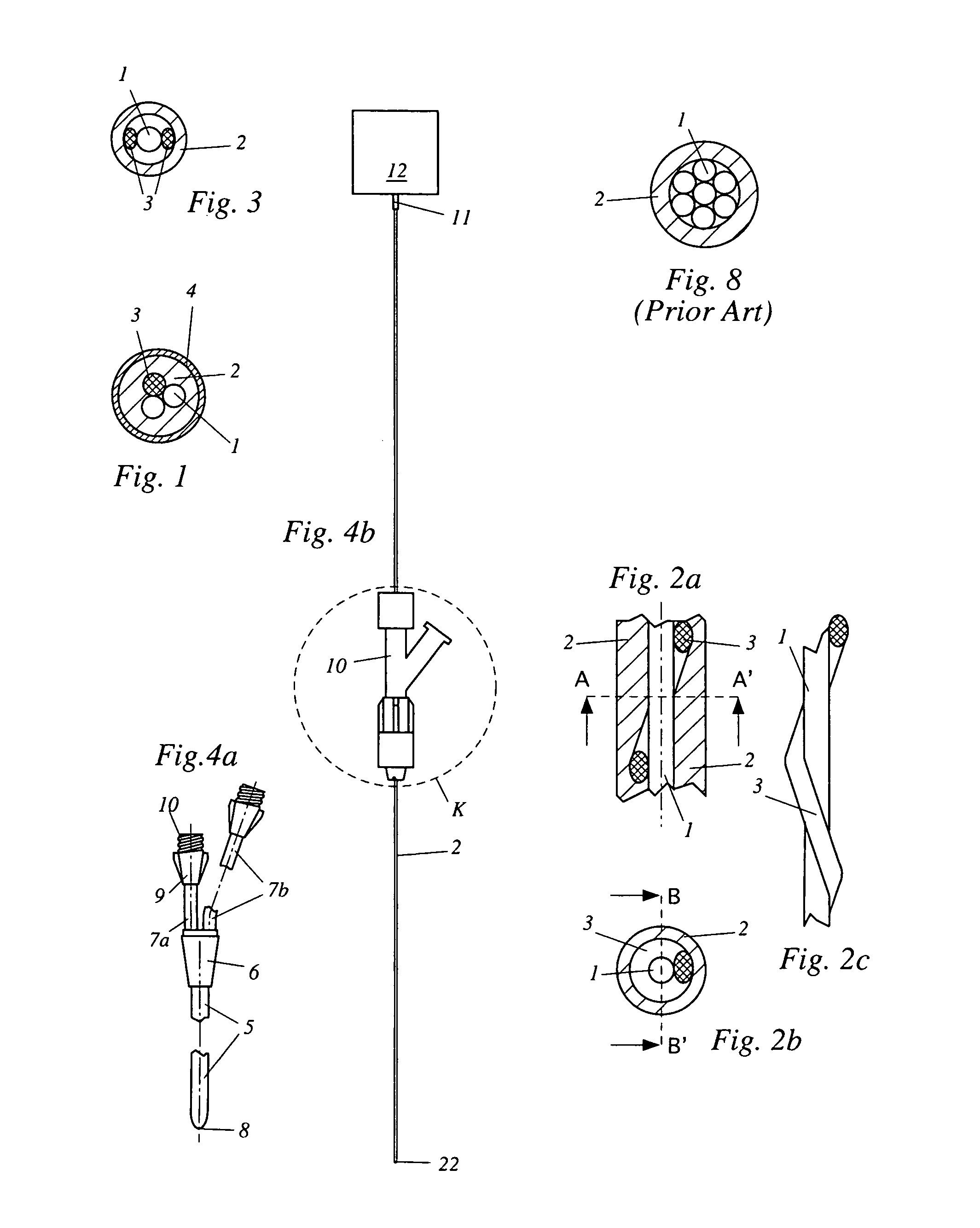
[0049]FIG. 1 shows a small diameter probe according to the present invention wherein the fiber-optical core 1 comprises only two fibers. A reinforcement fiber 3 improves stiffness, kink resistance and overall strength of the probe. The reinforcement fiber 3 is arranged essentially parallel to the core fibers 1. The outside of the sheath 2 is coated with an antithrombogenic coating 4 for reducing the danger of clots forming at the surface. The coating 4 may be comprised, for example, o...


PUM


Abstract

In a fiber-optic probe for intravascular measurements, e.g. oxygen saturation measurements, the fiber-optical core has only two fibers. A single fiber core is also possible. A reinforcement fiber improves stiffness, kink resistance and overall strength of the probe. The reinforcement fiber is arranged essentially parallel to the core fibers. The reinforcement fiber may also be wound around the core in a helical manner thus improving the mechanical properties to an even higher degree. The outside of the sheath is coated with an antithrombogenic coating for reducing the danger of clots forming at the surface. The reinforcement fiber may be made of carbon, metal, ceramics or aramide.

Description

CROSS REFERENCE TO RELATED APPLICATIONS[0001]Applicants claim priority under 35 U.S.C. §119 of European Application No. 08162826.5 filed Aug. 22, 2008.BACKGROUND OF THE INVENTION[0002]The present invention relates to fiber-optic probes, in particular to fiber-optic probes for intravascular measurements comprising a fiber-optic core for conducting electro-magnetic radiation from a proximal end of said probe to a distal end of said probe and a sheath made of synthetic sheath material and disposed around said core. The present invention further relates to fiber-optic probe assembly comprising such a fiber-optic probe and an intravascular catheter, the latter comprising a probe lumen having a proximal opening and a distal opening and being adapted to accommodate said fiber-optic probe.[0003]Fiber-optic probes of the kind initially mentioned are well-known from the prior art. An important application thereof is the optical in situ measurement of the oxygen saturation of blood, in particu...

Claims


Application Information

Patent Timeline
Patent Type & Authority Patents(United States)
IPC IPC(8): A61B5/1455
CPCA61B5/14542A61B5/1459G02B6/443
Inventor VEECK, MARCUSGOEDJE, OLIVERHERZ, ROBERTTHALMEIER, THOMASMANEGOLD, CHRISTOPHBOHN, MATTHIAS
Owner PULSION MEDICAL SYSTEMS SE
Why Eureka
Try Eureka