
Fastening and joining element for heat exchangers, and heat exchanger assembly in a motor vehicle

a technology of fastening and joining elements and heat exchangers, which is applied in the direction of heat exchanger casings, stationary conduit assemblies, lighting and heating apparatus, etc., can solve the problems of heat exchangers that cannot be adapted specifically, heat exchanger fastening, soldering, etc., and achieves a low production cost and easy assembly. , the effect of reducing the production cos

Inactive Publication Date: 2013-09-03
HBPO
View PDF25 Cites 5 Cited by
  • Summary
  • Abstract
  • Description
  • Claims
  • Application Information

AI Technical Summary

Benefits of technology

The present invention provides a simple and cost-effective solution for fastening heat exchangers to each other and to an assembly carrier in a motor vehicle. The fastening and connecting element is composed of a receiving opening and a fastening part with a U-shaped profile that can be easily joined to a mating part. The fastening part has a self-tapping screw which secures it to the assembly carrier. The receiving opening is adapted to the heat exchanger being fastened and can hold it without play. The fastening element can be easily produced and used with minimal production expenditure. The invention also allows for the connection of heat exchangers in a structural unit or module, and provides tolerance compensation between the heat exchangers and the assembly carrier.

Problems solved by technology

A problem with cooling modules of said type is the fastening of the heat exchangers to one another and with respect to a module carrier or assembly carrier.
In other heat exchangers which are composed entirely of metal parts, for example fully-aluminum heat exchangers, said favorable fastening possibilities do not exist, and it is in fact necessary for brackets to additionally be fastened to the fully-metal heat exchangers, for example by means of soldering, which is expensive.
A disadvantage of the known fastening is that the heat exchangers must be adapted specifically to the selected type of fastening, that is to say they must be provided with specific retaining pins.
A disadvantage of said type of fastening is likewise that the heat exchangers must be fitted with additional fastening elements, in this case mounting pins, which makes the production of said heat exchangers more expensive.
A disadvantage of said solution is the additional structural and production-related expenditure which is necessary for the attachment of the additional retaining lugs to the condenser.

Method used


Image

  • Fastening and joining element for heat exchangers, and heat exchanger assembly in a motor vehicle
  • Fastening and joining element for heat exchangers, and heat exchanger assembly in a motor vehicle
  • Fastening and joining element for heat exchangers, and heat exchanger assembly in a motor vehicle

Examples


Embodiment Construction

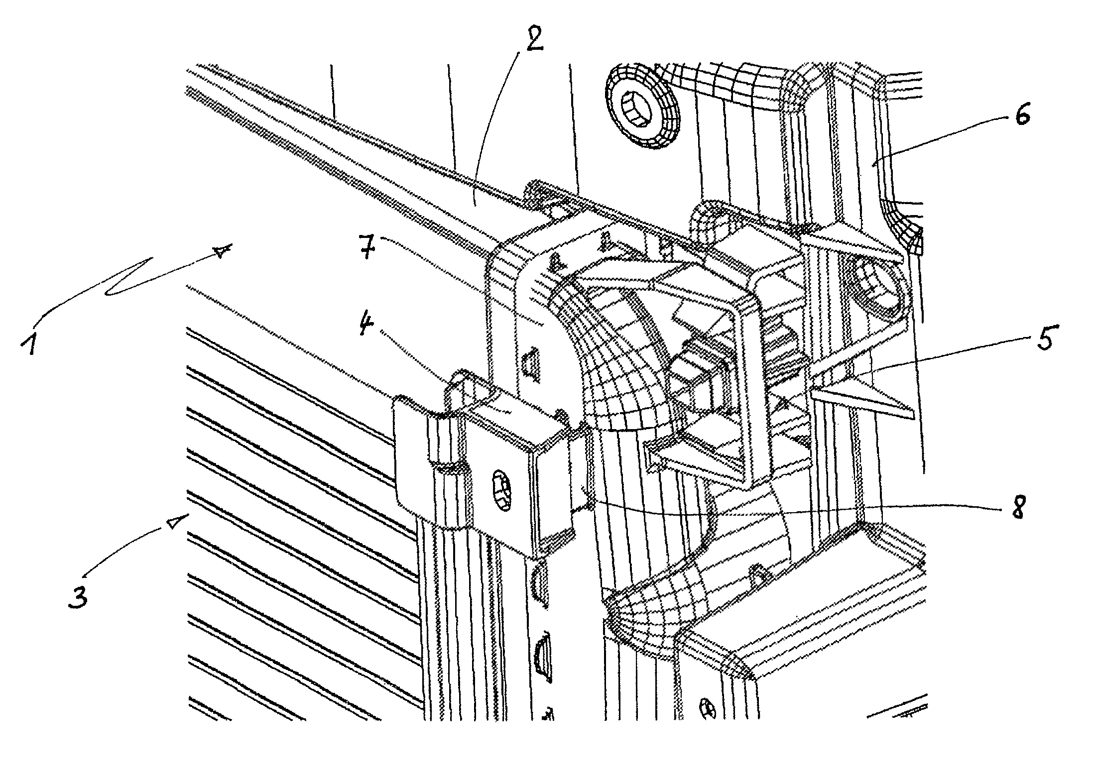
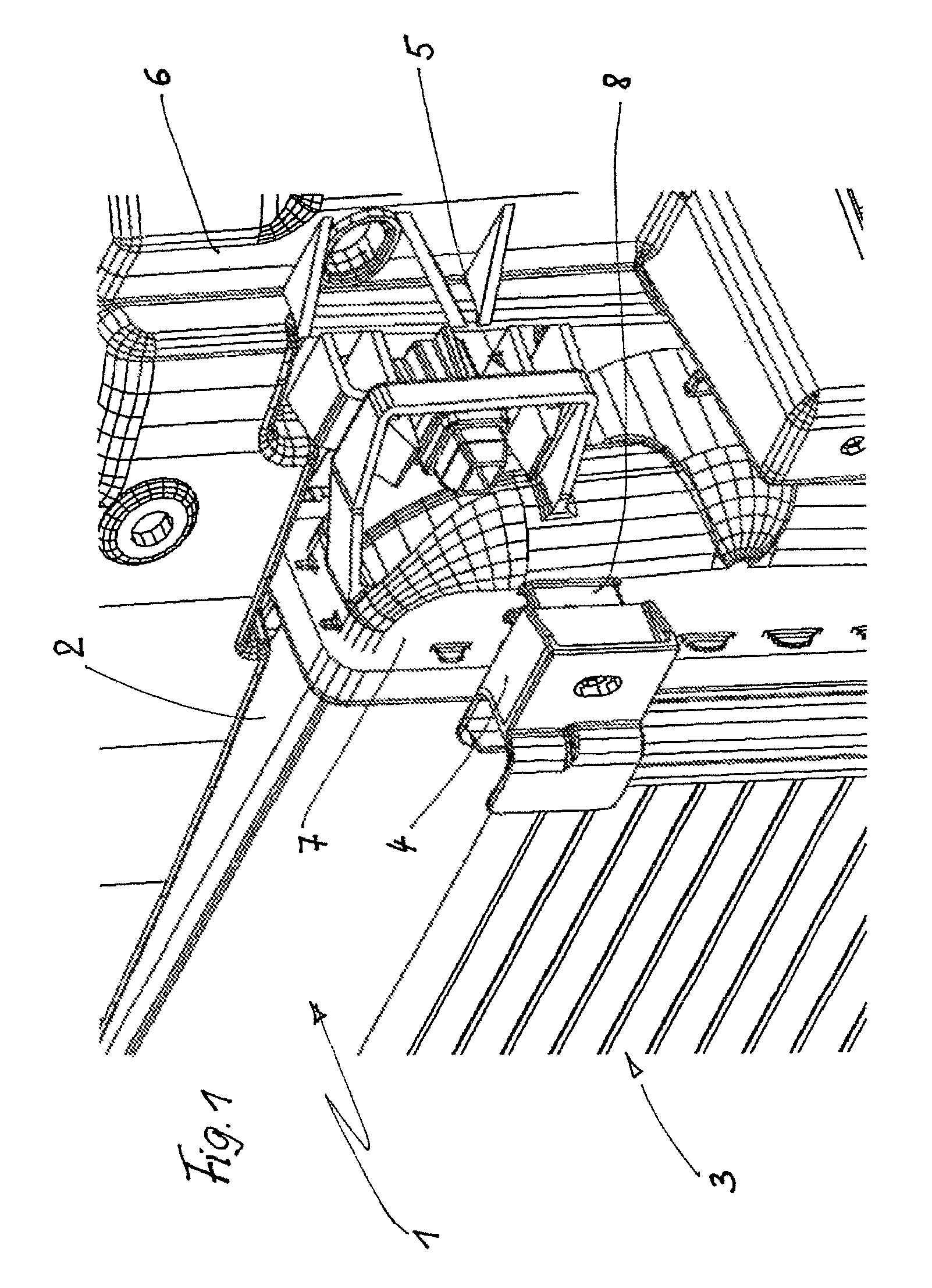
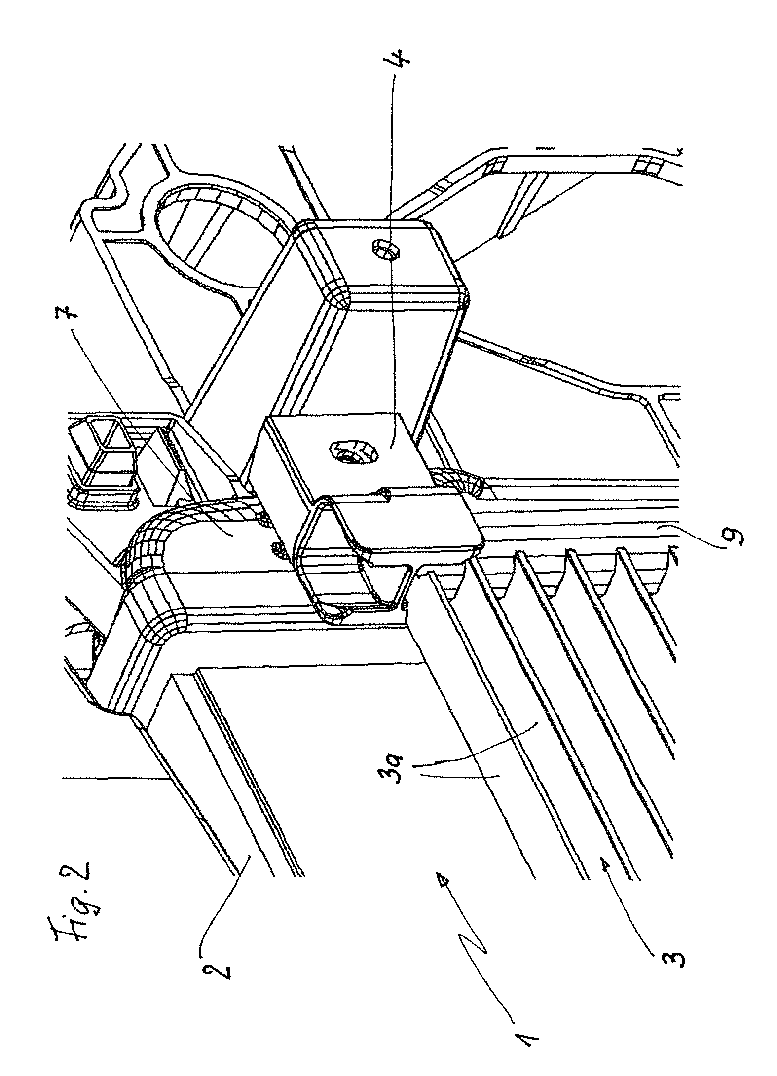
[0023]FIG. 1 shows a detail of a cooling module 1 in an isometric illustration. The cooling module 1 is composed of a mechanically produced coolant cooler 2 and a soldered condenser of fully-aluminum design. The two heat exchangers 2, 3 are connected to one another by means of a fastening and connecting element 4, while the coolant cooler 2, referred to below for short as the cooler 2, is connected to a module or assembly carrier 6 by means of a latching connection 5 which is not explained in any more detail. The cooler 2 is therefore the carrier for the condenser 3, while the module carrier 6 is the carrier for the entire cooling module with respect to a motor vehicle (not illustrated). Instead of the module carrier 6, it is likewise possible for an assembly carrier of a front module (not illustrated) to be the carrier of the cooling module 1. The cooler 2 has a coolant tank 7 composed of plastic, on the longitudinal side, which faces toward the condenser 3, of which a screw dome 8...


PUM


Abstract

The invention relates to a fastening and joining element (4) for fixing and connecting heat exchangers of a heat exchanger assembly in a motor vehicle. Said fastening and joining element (4) comprises at least one hole (4b) for positively accommodating a heat exchanger as well as a fastening part (4a) encompassing a profiled fastening member.

Description

[0001]The invention relates to a fastening and connecting element and to an arrangement of heat exchangers in a motor vehicle.BACKGROUND[0002]Arrangements of heat exchangers in a motor vehicle are known as so-called cooling modules, that is to say as a pre-assembled structural unit, which is for example composed of a coolant cooler, a refrigerant condenser, a charge-air cooler and / or an oil cooler which are cooled at the secondary side by ambient air. The cooling module can also be connected to a so-called assembly carrier and expanded to form a front module which includes additional components such as the headlights of the vehicle. A problem with cooling modules of said type is the fastening of the heat exchangers to one another and with respect to a module carrier or assembly carrier. If the heat exchangers have collecting tanks composed of plastic, that is to say for example coolant coolers, it is possible for fastening elements to be injection-molded, from plastic, onto the wate...

Claims


Application Information

Patent Timeline
Patent Type & Authority Patents(United States)
IPC IPC(8): F28F9/00B60K11/04
CPCB60H1/00521F28D1/0435F28F9/002
Inventor KERSTING, DIRKSCHMIDT, ANDREKORTE, WALTER
Owner HBPO
Learn More