Clamp member, clamp and anastomotic apparatus

a technology of anastomosis apparatus and clamp, which is applied in the direction of surgical staples, paper/cardboard containers, surgical forceps, etc., can solve the problems of complicated execution sequences and injury to biological tissues, and achieve efficient and stable anastomosis of organ tissue, stable holding, and easy and efficient gripping

Inactive Publication Date: 2013-09-03
SENKO MED INSTR MFG CO LTD
View PDF14 Cites 210 Cited by
  • Summary
  • Abstract
  • Description
  • Claims
  • Application Information

AI Technical Summary

Benefits of technology

[0076]The clamp members according to the present invention prevent the unintentional release of the organ tissue from the pointed teeth and the rake teeth when the organ tissue is being everted, so that the organ tissue gripped by the clamp members can be stably held.
[0077]The clamp according to the present invention enables easy and efficient gripping and everting of the clamped organ tissue by means of the organ gripping mechanism and the everting mechanism of the respective clamp members composing the clamp.
[0078]The anastomotic apparatus according to the present invention enables efficient and stable anastomosis of the organ tissue.

Problems solved by technology

As a result, it is possible for the gripping teeth to cause damage by coming into contract with an object or to cause injury by coming into contact with the operator.2) Although there are levers for carrying out a variety of operations, the execution sequences are complicated, such that the operator requires suitable proficiency in the various operations.3) There is a possibility of injury to the biological tissue in the case where an error is made in the operation sequence during anastomosis.

Method used


Image

  • Clamp member, clamp and anastomotic apparatus
  • Clamp member, clamp and anastomotic apparatus
  • Clamp member, clamp and anastomotic apparatus

Examples


first embodiment

[0187]the present invention will now be explained with reference to the accompanying figures.

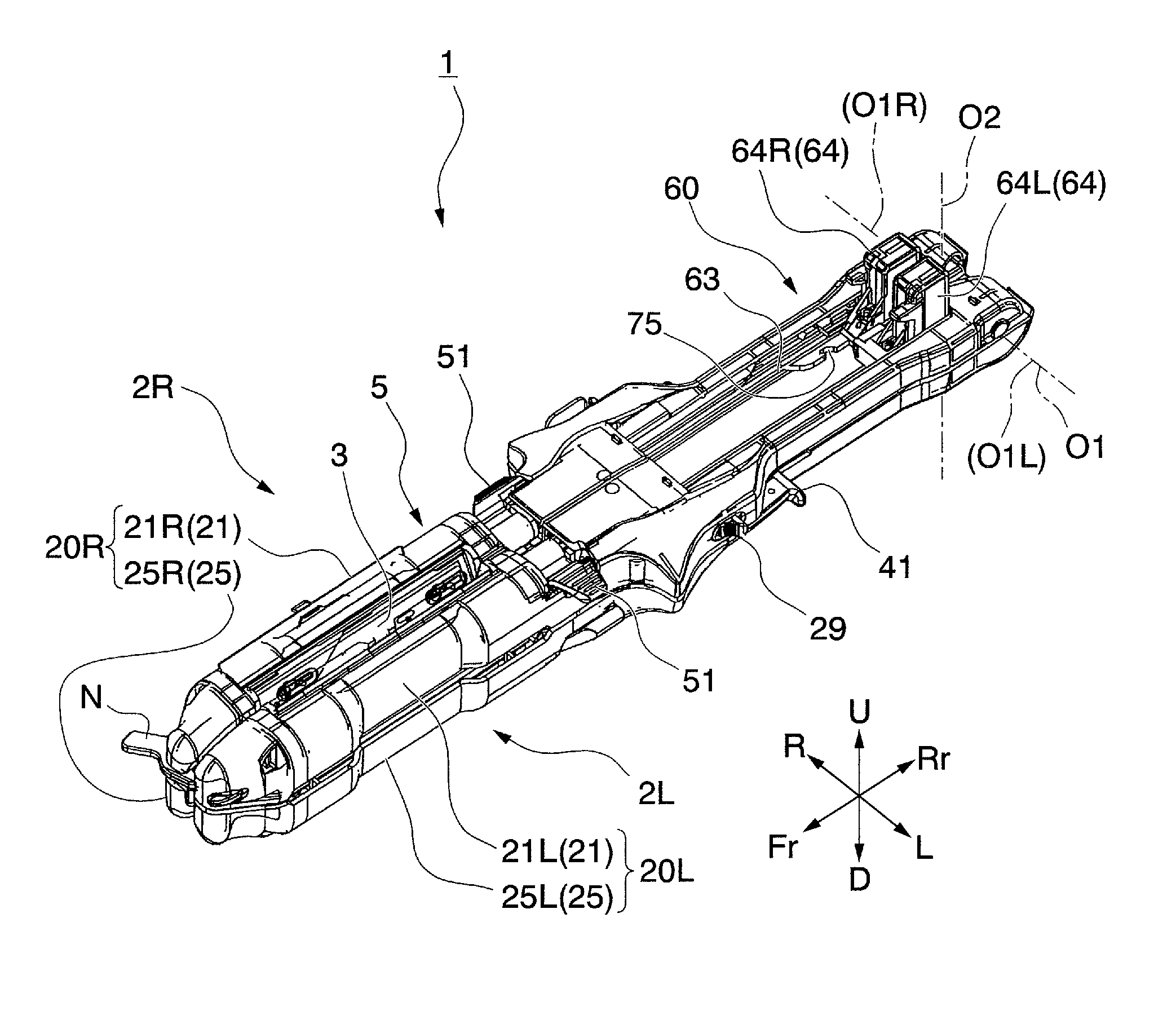
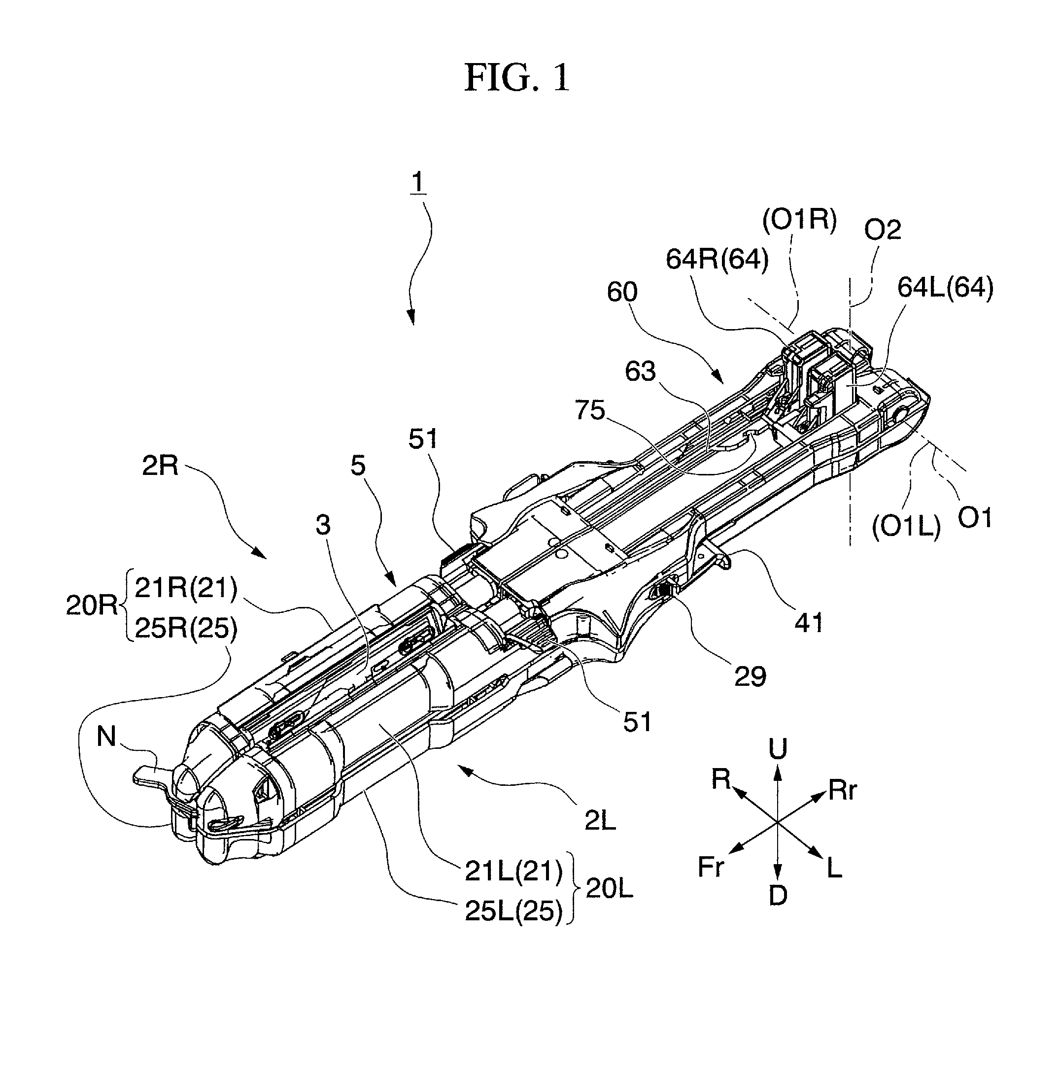
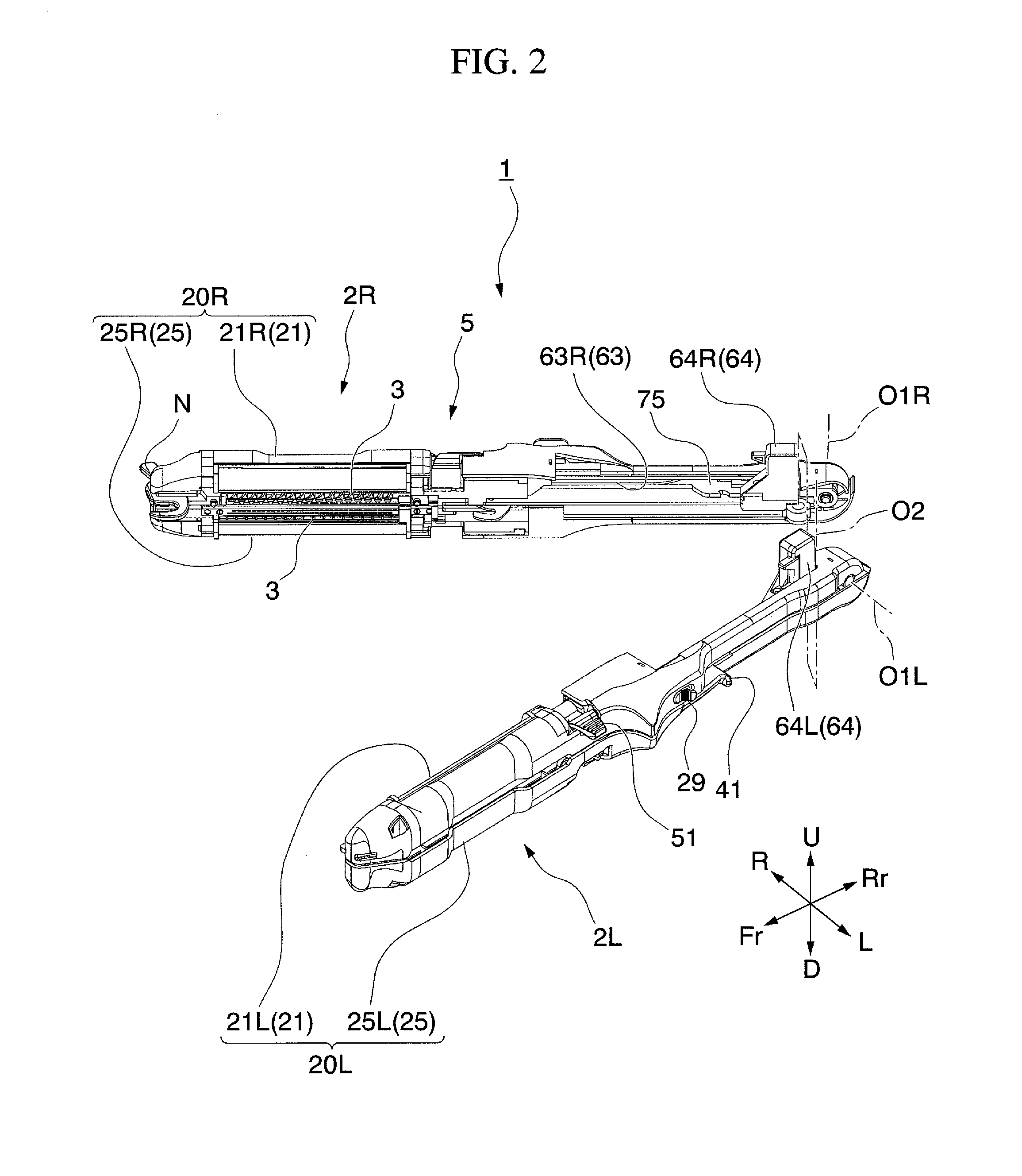
[0188]FIGS. 1 through 3 are views showing the anastomotic apparatus according to the present invention. The numeric symbol 1 indicates the anastomotic apparatus while numeric symbols 2R and 2L indicate the clamps.

[0189]FIGS. 4 and 5 show paired clamp members 20R (composed of clamp member 21R and clamp member 25R) which form clamp 2R, and paired clamp members 20L (composed of clamp member 21L and clamp member 25L) which form clamp 2L. FIG. 6 shows clamp member 25L.

[0190]The numeric symbols R, L, Fr, Rr, U and D on the coordinate axes shown in FIGS. 1 through 6 indicate direction associated with the anastomotic apparatus 1 and its composing members, with right (R), left (L), Fr (distal end side), up (U) and down (D) indicated for the case when the rear side Rr (referred to as the “handheld side” hereinafter) of the anastomotic apparatus 1 is held in the hand.

[0191]As shown in FIGS. 1 through 3...

second embodiment

[0354]Next, the present invention will be explained with reference to the figures.

[0355]FIGS. 37 and 38 are views showing the anastomotic apparatus according to the present invention. Numeric symbol 101 indicates the anastomotic apparatus and numeric symbols 102R,102L indicate the clamps.

[0356]FIGS. 39 and 40 are views showing the paired clamp member 120R (formed from clamp member 121R and clamp member 125R) which composes the clamp 102R, and paired clamp member 120L (formed from clamp members 121L and clamp members 125L) which composes the clamp 102L. FIG. 41 is a view showing the clamp member 125L.

[0357]The symbols R, L, Fr, Rr, U and D along the coordinate axes shown in FIGS. 37 through 41 show directions associated with anastomotic apparatus 1 and its composing members, and shows right (R), left (L), Fr (front), up (U) and down (D) when the rear Rr (“handheld side” hereinafter) of the anastomotic apparatus 1 is held on the handheld side.

[0358]As shown in FIGS. 37 and 38, the ana...


PUM

PropertyMeasurementUnit
angleaaaaaaaaaa
relative movementaaaaaaaaaa
surgical timeaaaaaaaaaa

Abstract

The anastomotic apparatus is equipped, in a fork which extends in the stapling direction, with an organ gripping mechanism which has a first gripping teeth plate member, a second gripping teeth plate member, a housing, and a clamping teeth drive section connected to at least the aforementioned first gripping teeth plate member or the second gripping teeth plate member to move the first gripping teeth plate member and the second gripping teeth plate member relative to each other by one unit space in the longitudinal direction, and is configured to clamp near a section of an organ to be stapled; an extroverting mechanism configured to move the aforementioned organ gripping mechanism within a turn-out movement range; and a grip controlling mechanism. With the anastomotic apparatus, the burden on the organ tissue can be reduced.

Description

TECHNICAL FIELD[0001]The present invention relates to a clamp member, clamp and anastomotic apparatus for gripping organ tissue in order to perform stapling and anastomosis of a digestive organ or the like during a surgical procedure.[0002]Priority is claimed on Japanese Patent Application Nos. 2008-329866 and 2008-329867, filed Dec. 25, 2008, the content of which is incorporated herein by reference.BACKGROUND ART[0003]When there is diseased tissue present in a hollow viscera (organ tissue, etc.) such as the intestine or stomach in the field of gastroenterological surgery, it is well understood that a restorative procedure is necessary following resection of that diseased site, in order to recreate a continuous digestive tract through end-to-end (end-to-end anastomosis), end-to-side (end-to-side anastomosis), or side-to-side (side-to-side anastomosis) stapling and anastomosis of the remaining normal regions of the hollow viscera.[0004]With regard to anastomotic techniques from among...

Claims


Application Information

Patent Timeline
Patent Type & Authority Patents(United States)
IPC IPC(8): A61B17/28
CPCA61B17/07207A61B17/1152A61B2017/1121A61B2017/07214
Inventor ISHITSUKI, MITSURUOCHIAI, YUJISHIBA, MIKIOSATO, SUEKICHIAKOPOV, ERNEST MIKHAJLOVICHSHIRAKAWA, MAKOTO
Owner SENKO MED INSTR MFG CO LTD
Why Eureka
Try Eureka