Rotary engine expansion chamber apparatus and method of operation therefor
What is AI technical title?
AI technical title is built by Patsnap AI team. It summarizes the technical point description of the patent document.
a technology of expansion chamber and rotary engine, which is applied in the direction of machines/engines, liquid fuel engines, lighting and heating apparatus, etc., can solve the problems of large amount of pollutants released into the atmosphere, small percentage of potential energy released, and poor efficiency of all internal combustion engines
Active Publication Date: 2013-09-03
PEKRUL MERTON W
View PDF146 Cites 121 Cited by
Summary
Abstract
Description
Claims
Application Information
AI Technical Summary
This helps you quickly interpret patents by identifying the three key elements:
Problems solved by technology
Method used
Benefits of technology
Problems solved by technology
All internal combustion engines suffer from poor efficiency; only a small percentage of the potential energy is released during combustion as the combustion is invariably incomplete.
Even with the support system, a significant quantity of pollutants are released into the atmosphere as a result of incomplete combustion when using an internal combustion engine.
Because internal combustion engines depend upon the rapid and explosive combustion of fuel within the engine itself, the engine must be engineered to withstand a considerable amount of heat and pressure.
These are drawbacks that require a more robust and more complex engine over external combustion engines of similar power output.
The high rotational speeds present several engineering challenges that typically result in specialized designs and materials, which adds to system complexity and cost.
Further, to operate at low-to-moderate rotational speeds, turbine engines typically utilize a step-down transmission of some sort, which again adds to system complexity and cost.
Similarly, reciprocating engines require linkages to convert linear motion to rotary motion resulting in complex designs with many moving parts.
In addition, the linear motion of the pistons and the motions of the linkages produce significant vibration, which results in a loss of efficiency and a decrease in engine life.
To compensate, components are typically counterbalanced to reduce vibration, which again increases both design complexity and cost.
This diabatic expansion represents a loss of energy.
Method used
Image
Click on the blue label to locate the original text in one second.
Reading with bidirectional positioning of images and text.
Examples
Embodiment Construction
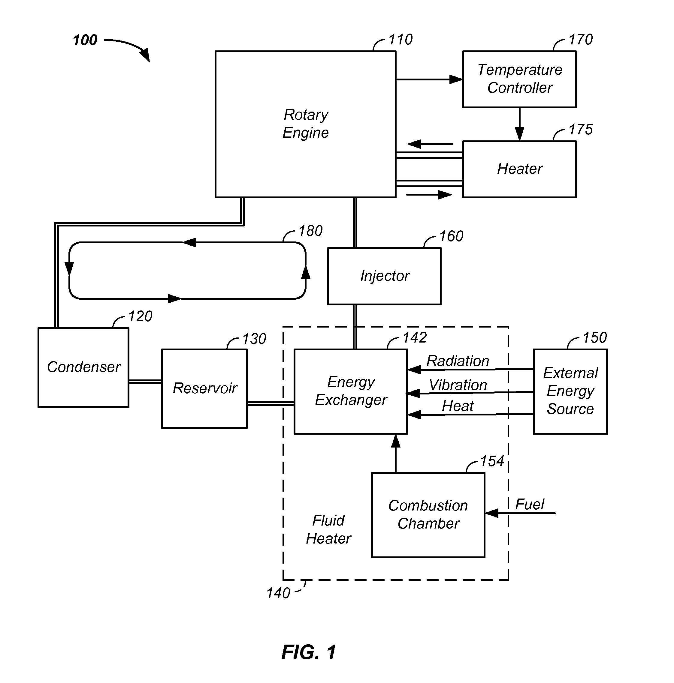
[0103]The invention comprises a rotary engine method and apparatus using an offset rotor. The rotary engine is preferably a component of an engine system using a recirculating liquid / vapor.
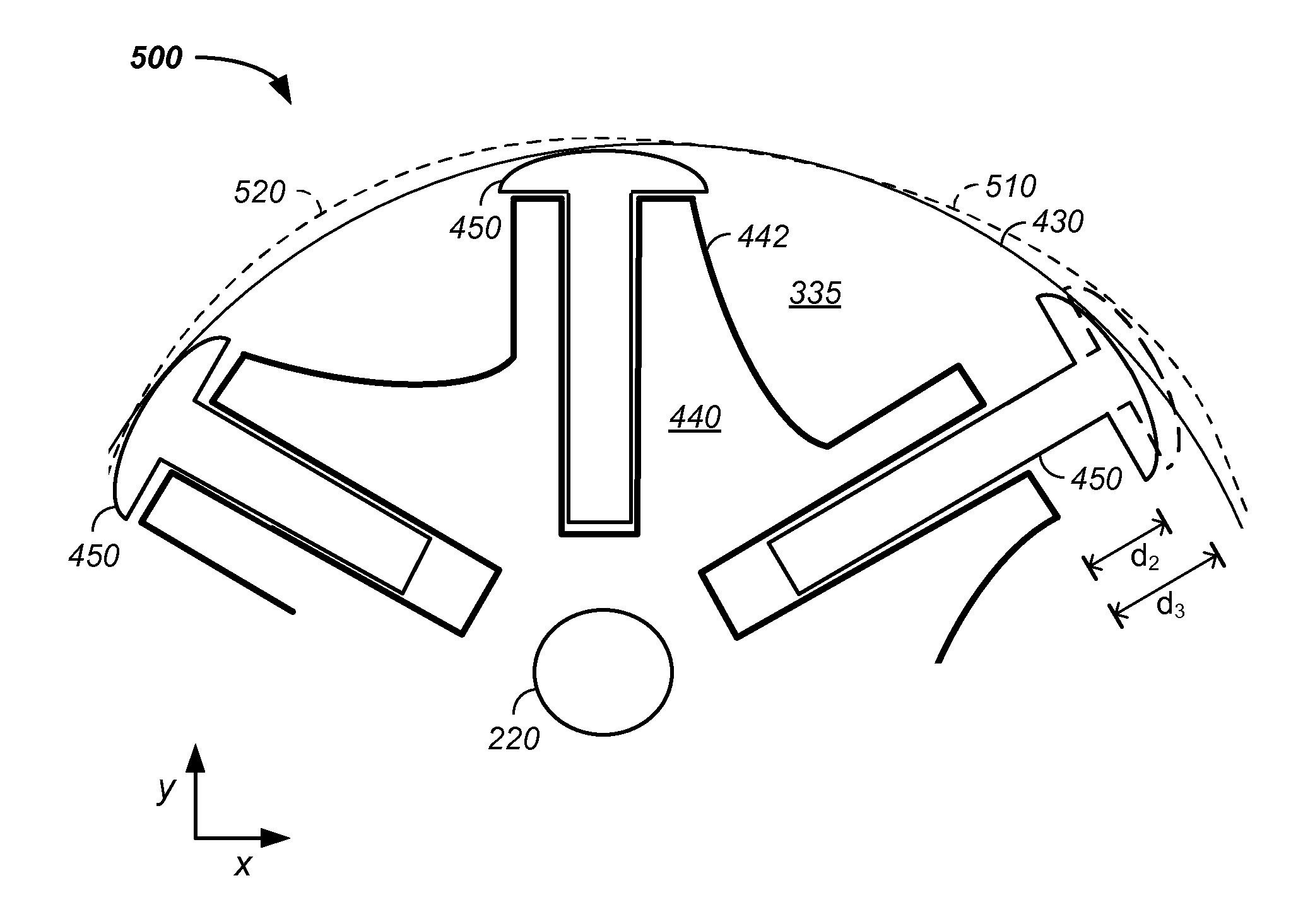
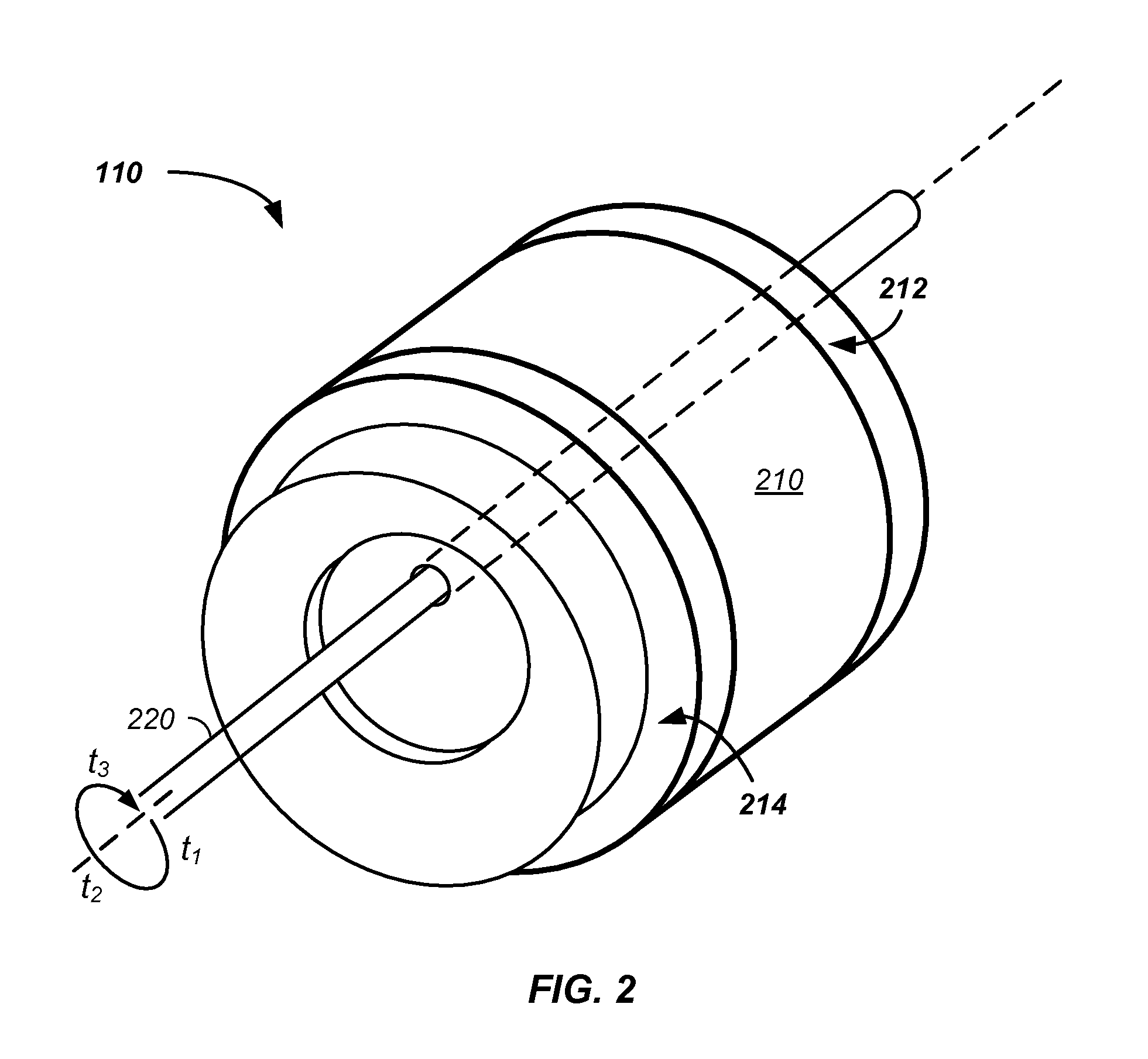
[0104]In one embodiment, an engine is described for operation on a fuel expanding about adiabatically in a power stroke of the engine. To aid the power stroke efficiency, the rotary engine contains one or more of a rotor configured to rotate in a stator, the rotor offset along both an x-axis and a y-axis relative to a center of the stator, a vane configured to span a distance between the rotor and the stator, where the inner wall of the stator further comprises at least one of: a first cut-out in the housing at the initiation of the power stroke, use of a build-up in the housing at the end of the power stroke, and / or use of a second cut-out in the housing at the completion of rotation of the rotor in the engine. The engine yields a cross-sectional area expanding during a portion of the power strok...
PUM
Abstract
An engine is described for operation on a fuel expanding about adiabatically in a power stroke of the engine. To aid the power stroke efficiency, the rotary engine contains one or more of a rotor configured to rotate in a stator, the rotor offset along both an x-axis and a y-axis relative to a center of the stator, a vane configured to span a distance between the rotor and the stator, where the inner wall of the stator further comprises at least one of: a first cut-out in the housing at the initiation of the power stroke, use of a build-up in the housing at the end of the power stroke, and / or use of a second cut-out in the housing at the completion of rotation of the rotor in the engine. The engine yields a cross-sectional area expanding during a portion of the power stroke at about the Fibonacci ratio.
Description
CROSS-REFERENCES TO RELATED APPLICATIONS[0001]This application:[0002]is a continuation-in-part of U.S. patent application Ser. No. 12 / 705,731 filed Feb. 15, 2010, now U.S. Pat. No. 8,375,720 which is a continuation of U.S. patent application Ser. No. 11 / 388,361 filed Mar. 24, 2006, now U.S. Pat. No. 7,694,520, which is a continuation-in-part of U.S. patent application Ser. No. 11 / 077,289 filed Mar. 9, 2005, now U.S. Pat. No. 7,055,327;[0003]claims the benefit of U.S. provisional patent application No. 61 / 304,462 filed Feb. 14, 2010;[0004]claims the benefit of U.S. provisional patent application No. 61 / 311,319 filed Mar. 6, 2010;[0005]claims the benefit of U.S. provisional patent application No. 61 / 316,164 filed Mar. 22, 2010;[0006]claims the benefit of U.S. provisional patent application No. 61 / 316,241 filed Mar. 22, 2010;[0007]claims the benefit of U.S. provisional patent application No. 61 / 316,718 filed Mar. 23, 2010;[0008]claims the benefit of U.S. provisional patent application ...
Claims
Application Information
Patent Timeline
Application Date:The date an application was filed.
Publication Date:The date a patent or application was officially published.
First Publication Date:The earliest publication date of a patent with the same application number.
Issue Date:Publication date of the patent grant document.
PCT Entry Date:The Entry date of PCT National Phase.
Estimated Expiry Date:The statutory expiry date of a patent right according to the Patent Law, and it is the longest term of protection that the patent right can achieve without the termination of the patent right due to other reasons(Term extension factor has been taken into account ).
Invalid Date:Actual expiry date is based on effective date or publication date of legal transaction data of invalid patent.

