Endoscopic electrosurgical jaws with offset knife

an electrosurgical and offset knife technology, applied in the field of electrosurgical jaws, can solve the problems of affecting the quality of endoscopic surgery, and affecting the effect of endoscopic surgery, so as to facilitate the substantially straight extension of the knife, prevent the binding of the knife, and facilitate the translation of the knife

Active Publication Date: 2013-09-03
TYCO HEALTHCARE GRP LP
View PDF1667 Cites 83 Cited by
  • Summary
  • Abstract
  • Description
  • Claims
  • Application Information

AI Technical Summary

Benefits of technology

[0012]In yet another embodiment, the offset knife channel and the disposition of the knife guide relative to the longitudinal axis facilitate substantially straight extension of the knife through the knife channel along a substantial length of the knife channel. This configuration helps prevent binding of the knife during translation through the knife channel. The proximal end of the knife channel may be offset a distance “X” relative to the longitudinal axis “A” defined through the forceps, wherein “X” is in the range of about 0.010 inches to about 0.040 inches. The knife channel may be defined within both the first and second jaw members and the knife guide is configured to preload the jaw members during assembly for ensuring proper alignment of the knife channels to facilitate translation of the knife therethrough.

Problems solved by technology

Smaller cannulas are usually preferred, which, as can be appreciated, ultimately presents a design challenge to instrument manufacturers who must find ways to make endoscopic instruments that fit through the smaller cannulas.
Due to the inherent spatial considerations of the surgical cavity, surgeons often have difficulty suturing vessels or performing other traditional methods of controlling bleeding, e.g., clamping and / or tying-off transected blood vessels.
However, if a larger vessel is ligated, it may be necessary for the surgeon to convert the endoscopic procedure into an open-surgical procedure and thereby abandon the benefits of endoscopic surgery.
In some instances, the knife blade is difficult to advance through the knife channel defined between jaw members or is subject to wear and tear over repeated use due to the relative position of the knife blade through the knife channel (contacting the sides of the knife channel).

Method used


Image

  • Endoscopic electrosurgical jaws with offset knife
  • Endoscopic electrosurgical jaws with offset knife
  • Endoscopic electrosurgical jaws with offset knife

Examples


Embodiment Construction

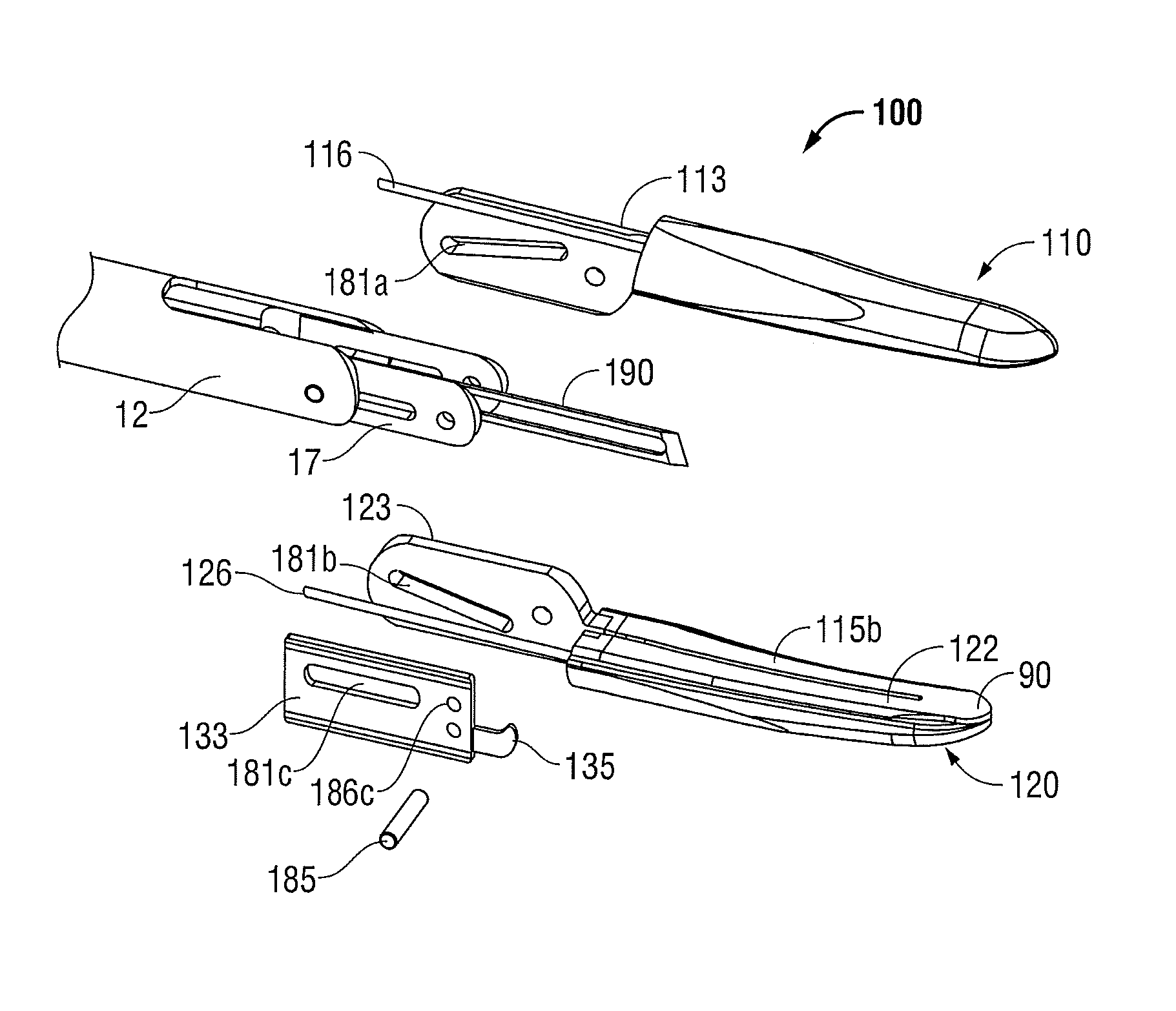
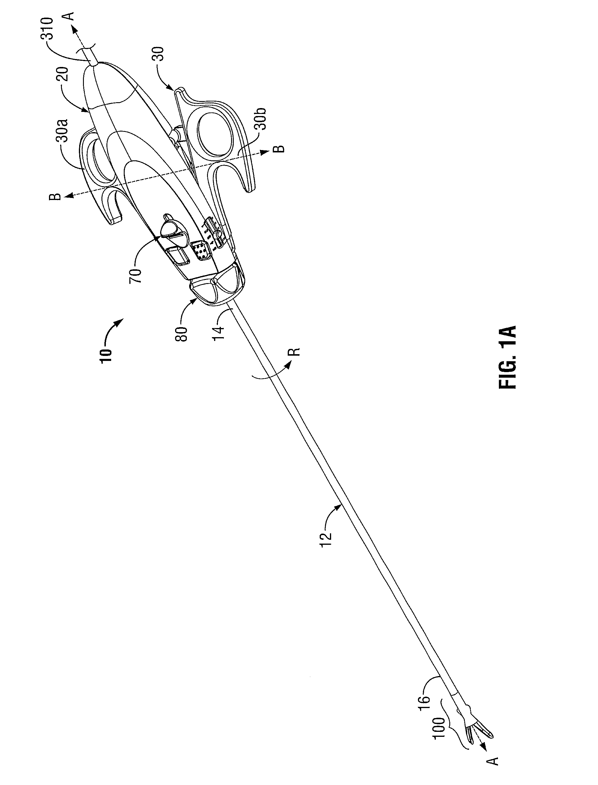
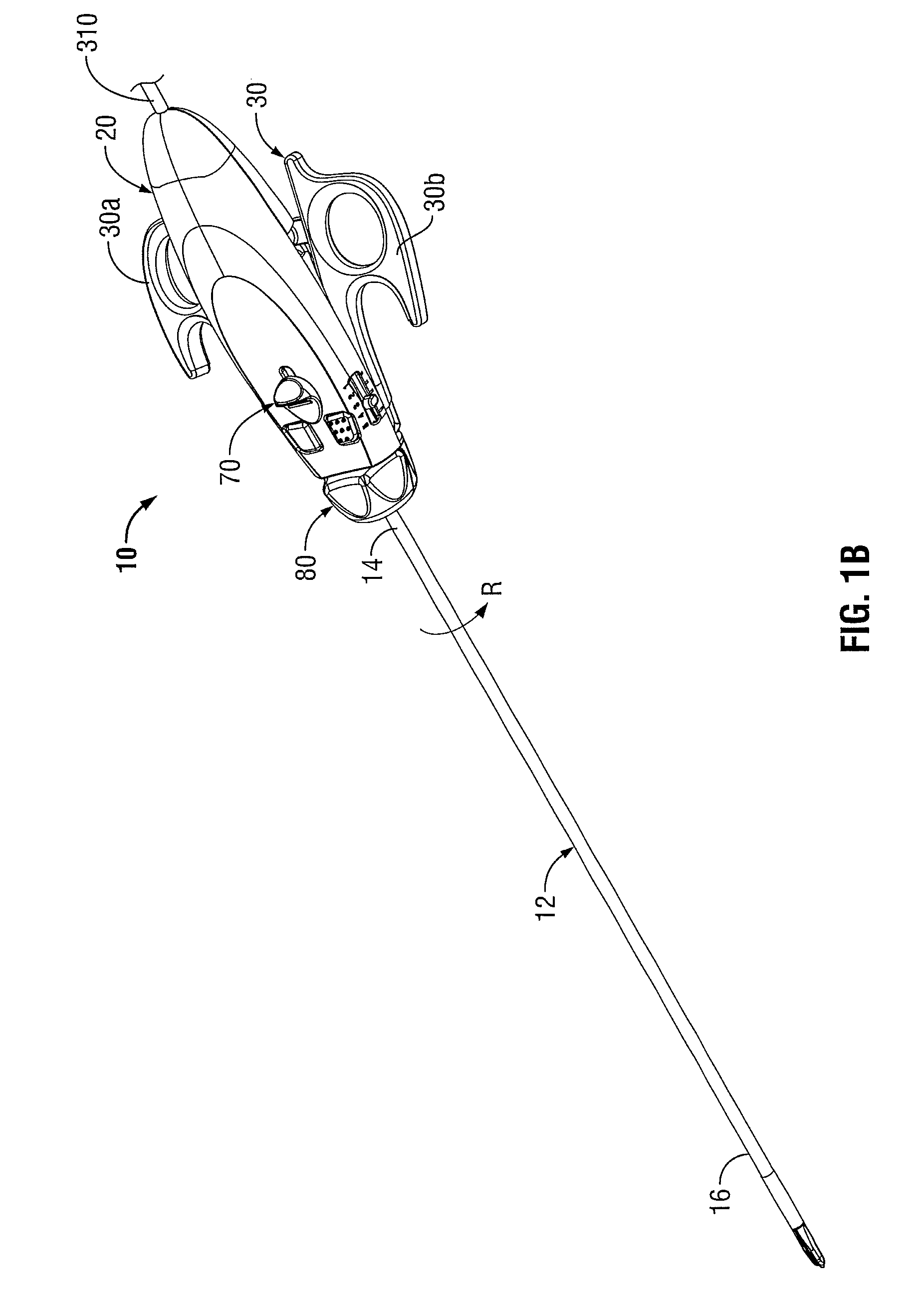
[0033]Turning now to FIGS. 1A and 1B, one embodiment of an electrosurgical forceps 10 is shown for use with various surgical procedures and generally includes a housing 20, a handle assembly 30, a rotating assembly 80, a knife trigger assembly 70 and an end effector assembly 100 which mutually cooperate to grasp, seal and divide tubular vessels and vascular tissue. Although the majority of the figure drawings depict a forceps 10 for use in connection with endoscopic or laparoscopic surgical procedures, the present disclosure may be used for more traditional open surgical procedures. For the purposes herein, the forceps 10 is described in terms of an endoscopic or laparoscopic instrument; however, it is contemplated that an open version of the forceps may also include the same or similar operating components and features as described below.

[0034]Forceps 10 includes a shaft 12 that has a distal end 16 dimensioned to mechanically engage the end effector assembly 100 and a proximal end ...


PUM


Abstract

A forceps includes an end effector assembly having first and second jaw members. Each jaw member includes a proximal flange having an inwardly-facing surface. The proximal flanges are coupled to one another for moving the jaw members relative to one another between a first position and a second position for grasping tissue therebetween. The inwardly-facing surfaces of the proximal flanges are disposed in abutting relation relative to one another. A knife is configured to move along a knife path defined along an outwardly-facing surface of one of the proximal flanges. The knife is movable between a retracted position and an extended position, wherein the knife extends between the jaw members to cut tissue grasped therebetween.

Description

CROSS-REFERENCE TO RELATED APPLICATIONS[0001]This application is a continuation of U.S. patent application No. 12,499,553, filed on Jul. 8, 2009, now U.S. Pat. No. 8,246,618, the entire contents of which are hereby incorporated by reference herein.BACKGROUND[0002]1. Technical Field[0003]The present disclosure relates to an electrosurgical jaws and, more particularly, to an elongated endoscopic electrosurgical forceps with an offset knife for sealing and / or cutting tissue.[0004]2. Background of Related Art[0005]Electrosurgical forceps utilize both mechanical clamping action and electrical energy to effect hemostasis by heating tissue and blood vessels to coagulate, cauterize and / or seal tissue. As an alternative to open forceps for use with open surgical procedures, many modern surgeons use endoscopic or laparoscopic instruments for remotely accessing organs through smaller, puncture-like incisions or natural orifices. As a direct result thereof, patients tend to benefit from less sc...

Claims


Application Information

Patent Timeline
Patent Type & Authority Patents(United States)
IPC IPC(8): A61B17/29A61B18/14
CPCA61B17/2909A61B17/295A61B18/1445A61B17/32A61N1/18A61B2017/2911A61B2017/2919A61B2017/2922A61B2017/2945A61B2017/320052A61B2018/00404A61B2018/00601A61B2018/0063A61B2018/1412A61B2018/1432A61B2018/1455A61B2019/304A61B2090/034
Inventor BUCCIAGLIA, JOSEPH D.CHOJIN, EDWARD M.HORNER, GLENN A.
Owner TYCO HEALTHCARE GRP LP
Why Eureka
Try Eureka