
Pipe module

a construction method and technology of a pipe module, applied in the direction of pipes, rigid containers, packaging, etc., can solve the problems of requiring a lot of time and man-hours, and a lot of working time for the disassembly operation, so as to facilitate the disassembly of an adhered and fixed temporary member without deteriorating safety

Inactive Publication Date: 2013-09-03
HITACHI LTD
View PDF2 Cites 0 Cited by
  • Summary
  • Abstract
  • Description
  • Claims
  • Application Information

AI Technical Summary

Benefits of technology

The present invention is about a construction method for a pipe module that can easily disassemble a temporary member without sacrificing safety. This invention also reduces the time for welding and disassembling, which helps to shorten construction work period. Overall, this invention provides a safer, efficient, and economical solution for assembling and disassembling pipe modules.

Problems solved by technology

Therefore, if the number of pipe modules to be used is increased, the temporary members are correspondingly increased, and there has been a problem that a lot of time and man-hours are required.
If the number of pipe modules to be used is increased, there is a problem that a lot of working time is required also for the disassembling operation.

Method used


Image

  • Pipe module
  • Pipe module
  • Pipe module

Examples


first embodiment

[0034](First Embodiment)

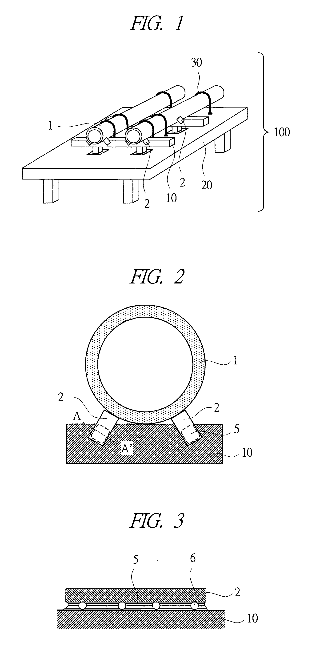
[0035]FIG. 1 is a schematic perspective view of a pipe module 100 to which a first embodiment of the present invention is applied. Note that the number of the members shown in the drawings is increased or decreased depending on the case and is not limited to those in the drawings.

[0036]As shown in FIG. 1, the pipe module 100 of the present embodiment has pipes 1, temporary parts 2, bases 10, a transporting base 20 and metal wires 30.

[0037]The pipe 1 is a pipe used for circulation of cooling water or the like for efficiently operating a power plant.

[0038]The temporary part 2 is a member for suppressing only the lateral misalignment in the positioning of the pipe 1.

[0039]The base 10 is a structural member for fixing the pipe 1.

[0040]An adhesive layer 5 shown in FIG. 2 is a layer of an adhesive agent which fixes the temporary part 2 and the pipe-fixing base 10.

[0041]The base 20 is a structural member for transporting the pipe module 100.

[0042]The metal wire 30 i...

second embodiment

[0074](Second Embodiment)

[0075]Next, a second embodiment of the present invention will be described with reference to drawings.

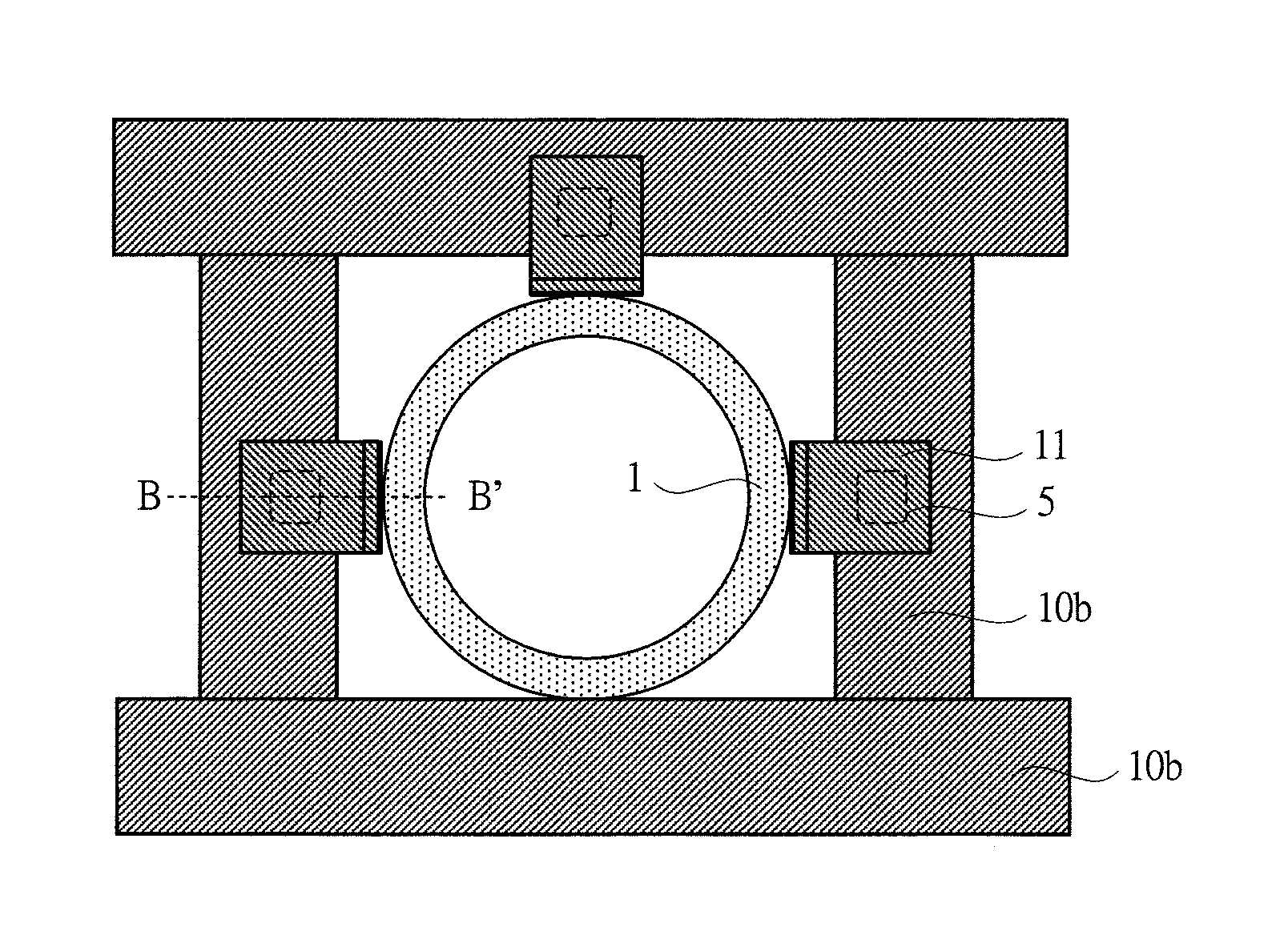
[0076]FIG. 6 is a schematic perspective view of a pipe module 101 to which the second embodiment of the present invention is applied. FIG. 7 is an example showing the entirety of the case where temporary parts 11 are provided at three locations of upper, right and left locations of a pipe-fixing support frame 10b, and FIG. 8 is an example showing the adhesive layer 5 of the case where the temporary part 11 is adhered and fixed to the pipe-fixing support frame 10b in an enlarged manner.

[0077]In this embodiment, the support frame 10b is used instead of the base 10 of the first embodiment. Moreover, the temporary part 11 is used instead of the temporary part 2.

[0078]The support frame 10b is a structural member for fixing the pipe 1. Different from the base 10, the support frame 10b is formed so as to surround the four sides of the pipe 1.

[0079]The temporary par...


PUM

PropertyMeasurementUnit
elastic modulusaaaaaaaaaa
diameteraaaaaaaaaa
sizeaaaaaaaaaa

Abstract

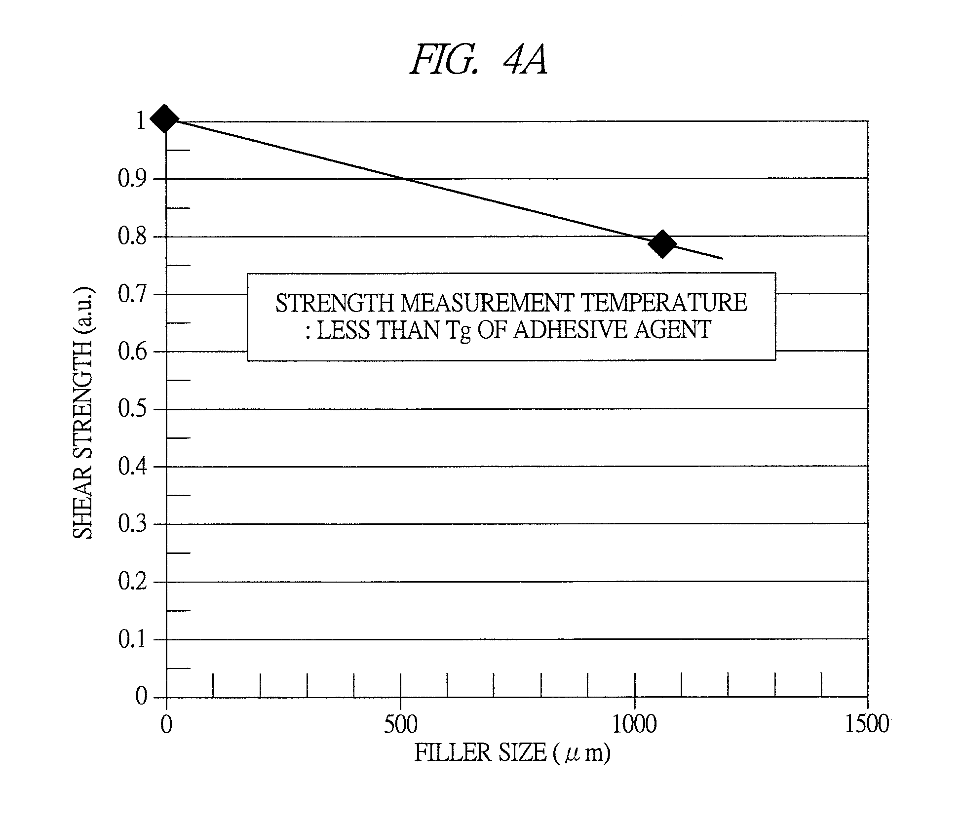
A temporary part is fixed to a base by using an adhesive layer to which fillers are mixed at a predetermined density. When the temporary part is heated, heat is applied to the fillers and the adhesive layer. At a temperature equal to or higher than the glass-transition temperature of the adhesive agent, the heated adhesive layer is thermally contracted so as to release remaining stress, and on the other hand, the heated fillers are thermally expanded. In this manner, the peel-off strength between the adhesive layer and the base (or the temporary part) is reduced, and the disassembly is facilitated.

Description

CROSS-REFERENCE TO RELATED APPLICATION[0001]The present application claims priority from Japanese Patent Application No. 2010-180899 filed on Aug. 12, 2010, the content of which is hereby incorporated by reference into this application.TECHNICAL FIELD OF THE INVENTION[0002]The present invention relates to a construction method of a pipe module for efficiently building a power plant such as a nuclear power plant, a thermal power plant, a hydraulic power plant or the like, and particularly relates to a method of removing a transporting member attached to the pipe module.BACKGROUND OF THE INVENTION[0003]In the construction of various power plants such as a nuclear power plant, a thermal power plant, a hydraulic power plant and the like, for the efficient construction of the power plant, pipes modularized in advance are transported to the plant construction site, and the modules are aligned with each other to mutually connect the pipes on the site.[0004]In order to efficiently carry out...

Claims


Application Information

Patent Timeline
Patent Type & Authority Patents(United States)
IPC IPC(8): B32B1/08B32B15/082B32B15/092
CPCC09J5/00C09J163/00Y10T428/1355C09J2433/00C09J2463/00Y10T428/1359Y10T428/1393Y10T428/1372Y10T428/139Y10T428/1386Y10T428/1397Y10T428/131
Inventor OOZEKI, YOSHIOARAI, SATOSHITSUNODA, SHIGEHARUYOTSUYA, TAIHEIIMAOKA, SHIZUO
Owner HITACHI LTD
Learn More