Door lock with idle travel in a locking state

a technology of locking state and lock, applied in the field of door locks, can solve the problems of damage to the components of the lock, the lock cannot be retracted to prevent unauthorized access,

Active Publication Date: 2013-09-10
I TEK METAL MFG
View PDF30 Cites 10 Cited by
  • Summary
  • Abstract
  • Description
  • Claims
  • Application Information

AI Technical Summary

Benefits of technology

[0004]The present invention solves this need and other problems in the field of preventing damage to components of door locks mounted to panic exit doors or passageway doors by providing a door lock including a bracket adapted to be fixed to a side of a door. The door is adapted to be pivotably mounted to a door frame having a stop. A latch is mounted to the bracket and pivotable about a first axis between an extended, latching position, and a retracted, unlatching position. A follower includes a first end pivotably connected to the latch and a second end spaced from the first end of the follower along a second axis perpendicular to the first axis. A linking rod includes first and second ends spaced along the second axis. The first end of the linking rod is pivotably connected to the second end of the follower. The second end of the linking rod is movable in an unlatching direction along the second axis for moving the latch from the extended, latching position, to the retracted, unlatching position, and movable in a latching direction opposite to the unlatching direction for moving the latch from the retracted, unlatching position, to the extended, latching position. First and second brackets are adapted to be fixed to the side of the door, and each includes a sliding slot extending along a third axis perpendicular to the first and second axes. The second bracket has a spacing to the bracket along the second axis larger than the first bracket. A third bracket is adapted to be fixed to the side of the door and located between the first and second brackets along the second axis.
[0009]When the draw bar is in the retracted position and when the operative member is operated to move the first and second pins along the third axis towards the door, the first and second follower elements pivot the first and second traction members about the first and second pivot axes. The second corners of the first and second traction members move the connecting member and the connecting rod in the unlatching direction. Movement of the follower plate in the unlatching direction is stopped by the first end of the stop member. The first groove of the follower plate allows movement of the peg in the unlatching direction without moving the follower plate. The push slot of the connecting member allows movement of the connecting member in the unlatching direction without moving the pin, preventing movement of the linking rod in the unlatching direction. The latch remains in the extended, latching position.
[0010]When the draw bar is in the extended position and when the latch is pressed by the stop on the door frame and pivoted from the extended, latching position to the retracted, unlatching position, the latch moves the follower element in the unlatching direction to move the linking rod in the unlatching direction. The linking rod causes the follower plate to move in the unlatching direction. The peg received in the first groove of the follower plate and the pin received in the second groove of the follower plate are not moved. The elongated slot of the follower plate allows movement of the follower plate relative to the third corner of the first traction member without pivoting the first traction member about the first pivot axis.

Problems solved by technology

When the door lock is in a locking state, the latch can not be retracted to prevent unauthorized access.
However, the press bar has a large area and, thus, imparts considerable force and causes damage to the components in the lock if the press bar is pressed with large force while the lock is in the locking state.

Method used


Image

  • Door lock with idle travel in a locking state
  • Door lock with idle travel in a locking state
  • Door lock with idle travel in a locking state

Examples


Embodiment Construction

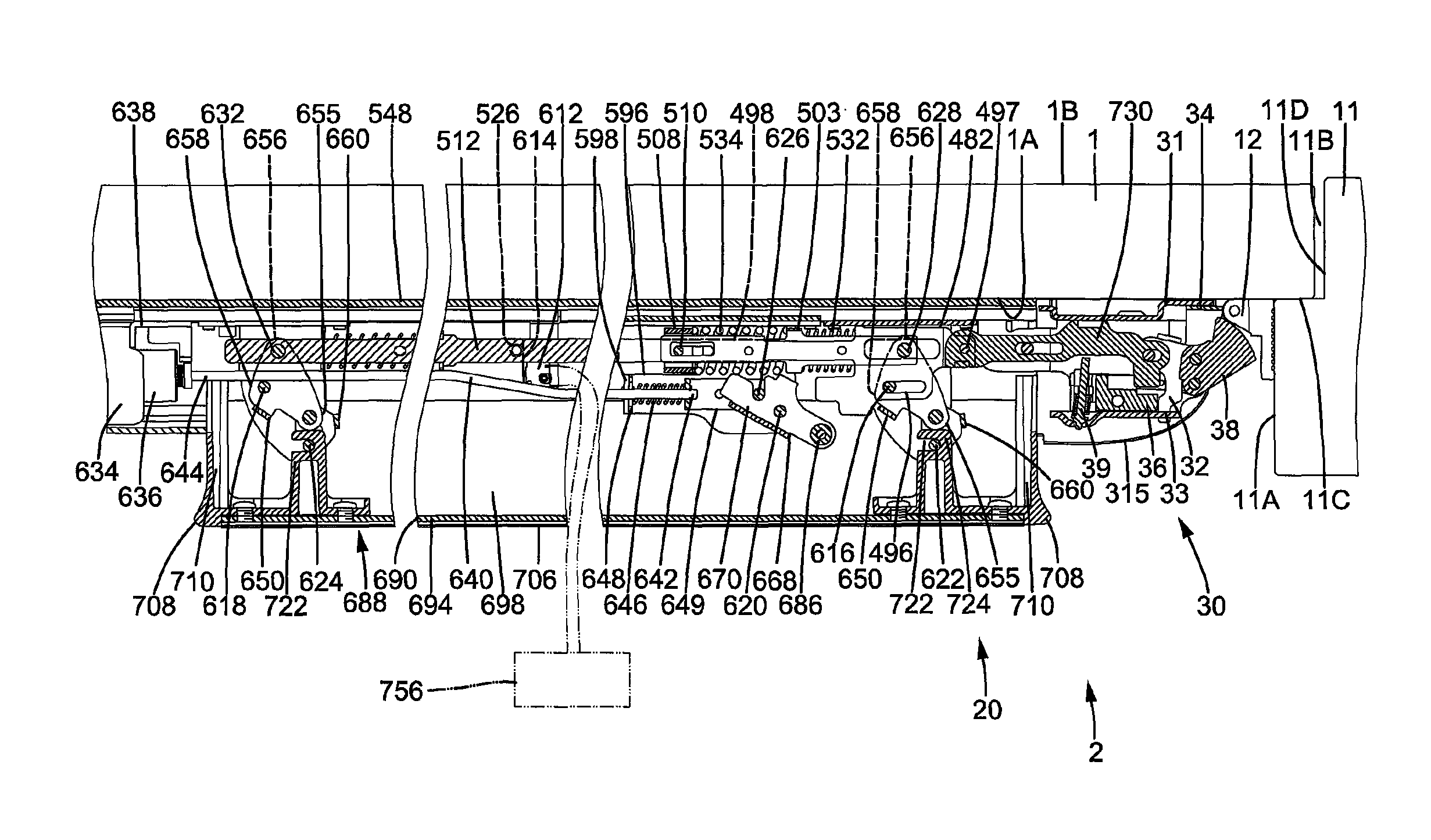
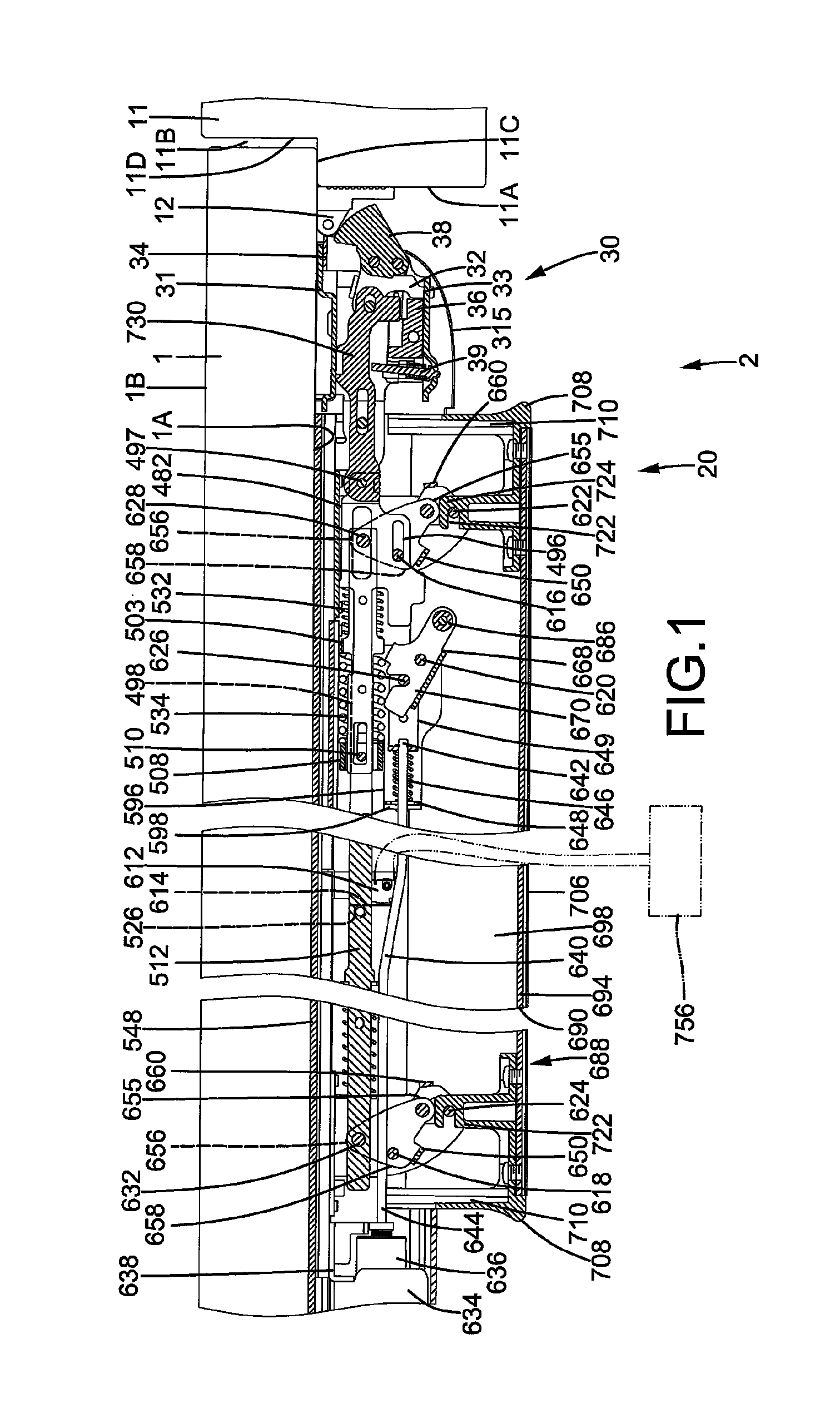
[0040]A door lock according to the present invention is shown in the drawings and generally designated 2. Door lock 2 includes an operational device 20 and a latch device 30 mounted to a door 1 pivotable relative to a door frame 11 having rectangular or inverted U-shaped cross sections. Door frame 11 is fixed to a wall of a passageway and includes an inner face 11A and a stepped portion 11B. Stepped portion 11B includes an abutment face 11C extending perpendicularly from an edge of inner face 11A and a face 11D extending perpendicularly to abutment face 11C and parallel to and spaced from inner face 11A. Door 1 includes first and second sides 1A and 1B. An end of door 1 is pivotably mounted to door frame 11, and door 1 is movable between an open position and a closed position. When door 1 is in the closed position, first side 1A of door 1 abuts abutment face 11C of door frame 11. An end face of the other end of door 1 adjacent to stepped portion 11B is spaced from abutment face 11C....


PUM


Abstract

A door lock (2) includes a linking rod (730) movable in an unlatching direction for moving a latch (38) to an unlatching position and movable in a latching direction for moving the latch (38) to a latching position. When a draw bar (640) is in an extended position and when an operative member (688) is operated, a follower plate (482) and the connecting rod (730) are moved in the unlatching direction through a connecting member (498) and a connecting rod (512). When the draw bar (640) is in a retracted position and when the operative member (688) is operated, the connecting member (498) and the connecting rod (512) are moved in the unlatching direction. Movement of the follower plate (482) in the unlatching direction is stopped by a stop member (668), preventing movement of the linking rod (730) in the unlatching direction and retaining the latch (38) in the latching position.

Description

BACKGROUND OF THE INVENTION[0001]The present invention relates to a door lock and, more particularly, to a door lock mounted on a panic exit door or a passageway door and having an idle travel when the door lock is in a locking state to avoid damage to the components of the door lock.[0002]A typical lock for a panic exit door or a passageway door generally includes a press bar that can be pressed to retract a latch for unlatching the door in emergency conditions as well as for normal passage. When the door lock is in a locking state, the latch can not be retracted to prevent unauthorized access. However, the press bar has a large area and, thus, imparts considerable force and causes damage to the components in the lock if the press bar is pressed with large force while the lock is in the locking state.[0003]Thus, a need exists for a door lock that has an idle travel when the door lock is in a locking state to avoid damage to the components of the door lock.BRIEF SUMMARY OF THE INVEN...

Claims


Application Information

Patent Timeline
Patent Type & Authority Patents(United States)
IPC IPC(8): E05B65/10
CPCE05B65/1053Y10T292/0909Y10T292/1055Y10T292/1076Y10T292/0908Y10T70/5159
Inventor SHEN, CHUN-MENG
Owner I TEK METAL MFG
Why Eureka
Try Eureka