Tool ratchet

a tool ratchet and tool technology, applied in the direction of wrenches, power-driven tools, screwdrivers, etc., can solve problems such as electric motor operation, and achieve the effect of preventing damage to components and minimizing wear of coupling components

Inactive Publication Date: 2008-05-22
ROBERT BOSCH GMBH
View PDF8 Cites 7 Cited by
  • Summary
  • Abstract
  • Description
  • Claims
  • Application Information

AI Technical Summary

Benefits of technology

[0015]Preferably, the switching mechanism that is actuatable via the single switch is designed such that the electric motor is not turned on until the coupling is engaged, i.e., after the non-positive connection has been established, thereby minimizing wear of coupling components caused by components that are already being driven. The switching mechanism is preferably simultaneously designed such that the electric motor is switched off before the coupling components are separated from each other and, therefore, the non-positive connection between the electric motor and the receiving piece is disconnected.
[0016]To protect the transmission and the electric motor from overload, it is provided in a refinement of the present invention that the coupling is designed as an overload coupling, which automatically disengages when a maximum load torque of, e.g., 0.5 Nm, is exceeded, thereby preventing damage to components.
[0017]It is advantageous to design the preferably single switch as a sliding switch, which interacts with a spring, preferably a leaf spring. The sliding switch glides along the spring, which is preferably provided with at least one slanted surface, by way of which the spring exerts a force on a first coupling component, which causes it to move in the direction of a second coupling component, thereby ultimately establishing a non-positive connection. During disengagement, the switch is slid in the opposite direction, which causes the spring load of the first coupling component to at least decrease, thereby moving the first coupling component away from the second coupling component—preferably by one of the springs which acts against the spring mentioned—and disconnecting the non-positive connection.
[0018]It is advantageous that the two coupling components are designed as gearwheels, so that the coupling also serves a transmission function when in the engaged state. One possibility for realizing a non-positive connection between the two gearwheels is to provide an end-face bolt on at least one of the two gearwheels, which may be accommodated in a corresponding recess located on the end face of the other gearwheel, by way of which a force may be transferred in the circumferential direction.
[0019]An overload coupling may be realized in a simple manner by positioning the bolt at a slant or by providing the bolt with an oblique angle, since, due to the slanted direction, a force component is provided in the direction away from the opposite gearwheel, i.e., in the disengagement direction.
[0020]According to an advantageous embodiment of the present invention, it is provided that the tool ratchet is provided with a direction switch, so that the direction of torque transfer and the freewheeling direction may be switched, thereby making it possible for the tool ratchet to be used to tighten and loosen screws or nuts. It is particularly advantageous when the direction of rotation of the electric motor may be switched simultaneously using the direction switch, in particular by using a polarity divider.

Problems solved by technology

The disadvantage of the known ratchet is that it must be operated with an electric motor.

Method used


Image

  • Tool ratchet
  • Tool ratchet
  • Tool ratchet

Examples


Embodiment Construction

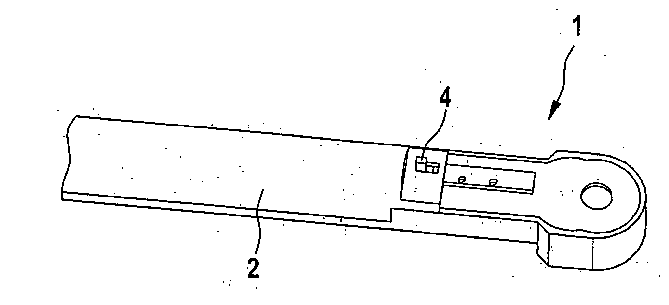
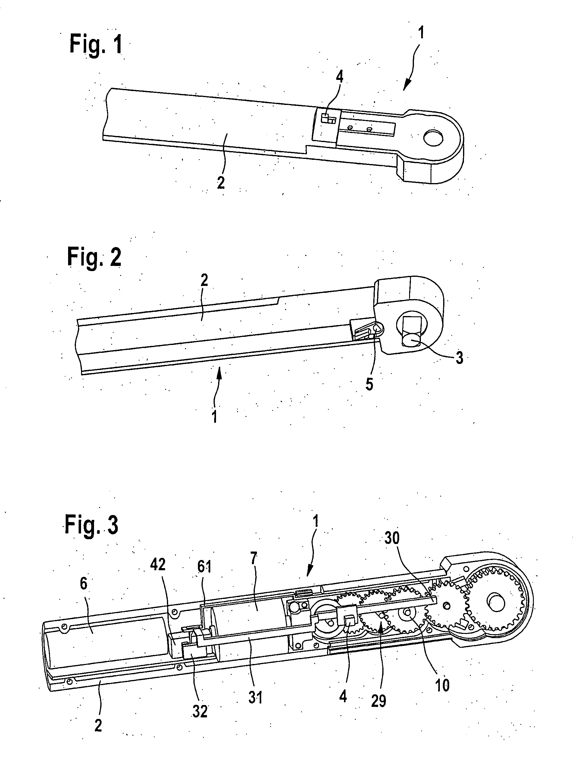
[0028]A tool ratchet 1 is shown in FIG. 1, in a perspective view from above. Tool ratchet 1 includes a longitudinal handle 2, with which torque may be applied in the circumferential direction to receiving piece 3 shown in FIG. 2. A switch 4 designed as a sliding switch is also shown, with which an electric motor—to be explained below—located inside handle 2 may be switched on and off, and with which a coupling—which will also be explained below—may be engaged and disengaged.

[0029]Tool ratchet 1 is shown in FIG. 2 in a view diagonally from below. A direction switch 5 is located on the underside, with which the direction of torque transfer may be switched. Receiving piece 3 has a square cross section for receiving a socket. Receiving piece 3 may have any type of contour, however, so that it may rotatably actuate pieces that have matching designs.

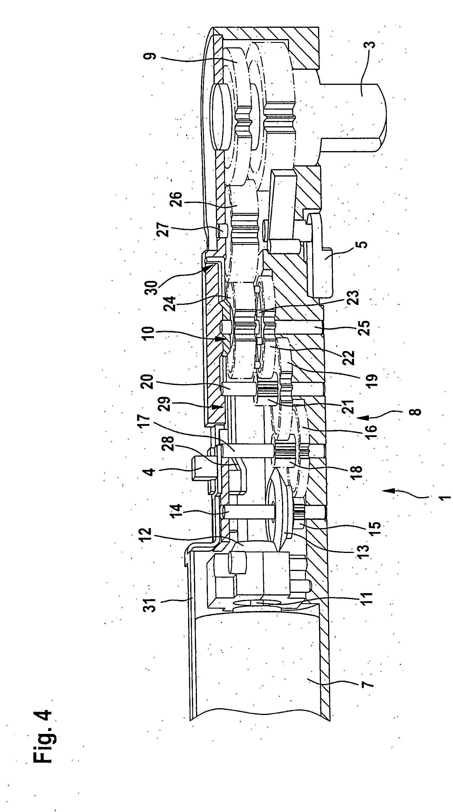
[0030]The inner mechanisms of tool ratchet 1 are shown in detail in a perspective view in FIGS. 3 and 4. A battery or a rechargeable battery ...


PUM


Abstract

A tool ratchet for tightening and loosening screws and/or nuts and the like, has a handle and a receiving piece operatively connected with handle via a ratchet mechanism, and with an electric motor, with which torque is transferrable to the receiving piece via a non-positive connection, and a coupling for disconnecting the non-positive connection.

Description

CROSS-REFERENCE TO A RELATED APPLICATION[0001]The invention described and claimed hereinbelow is also described in German Patent Application DE 102006054190.1 filed on Nov. 16, 2006. This German Patent Application, whose subject matter is incorporated here by reference, provides the basis for a claim of priority of invention under 35 U.S.C. 119(a)-(d).BACKGROUND OF THE INVENTION[0002]The present invention relates to a tool ratchet (ratchet) for tightening and loosening screws and / or nuts and the like.[0003]Tool ratchets are commonly known tools, for manually tightening and loosening screws or nuts in particular. A receiving piece is provided for receiving screws, nuts, or adapters (e.g., socket), which is adapted to the contour of the nut, screw, or the adapter, thereby enabling torque to be transferred. The receiving piece is connected with the handle via a ratchet mechanism—also referred to as a freewheel or locking pawl mechanism—such that, in one direction of rotation, torque ma...

Claims


Application Information

Patent Timeline
Patent Type & Authority Applications(United States)
IPC IPC(8): B25B23/16
CPCB25B21/00B25B13/463
Inventor HECHT, JOACHIMKRAUS, MARTIN
Owner ROBERT BOSCH GMBH
Why Eureka
Try Eureka