Linear quadratic regulator control for bleed air system fan air valve

a technology of bleed air system and regulator, applied in the field of valve control, can solve the problems of inability to achieve desirable transient responses of existing classical control methods, too high ambient temperature of some engine nacelles,

Active Publication Date: 2013-09-10
HONEYWELL INT INC
View PDF19 Cites 25 Cited by
  • Summary
  • Abstract
  • Description
  • Claims
  • Application Information

AI Technical Summary

Problems solved by technology

However, ambient temperatures in some engine nacelles may be too high for a suitable position feedback device.
Moreover, existing classical control methods on temperature may not exhibit desirable transient responses.

Method used


Image

  • Linear quadratic regulator control for bleed air system fan air valve
  • Linear quadratic regulator control for bleed air system fan air valve
  • Linear quadratic regulator control for bleed air system fan air valve

Examples


Embodiment Construction

[0018]The following detailed description is merely exemplary in nature and is not intended to limit the invention or the application and uses of the invention. Furthermore, there is no intention to be bound by any theory presented in the preceding background or the following detailed description.

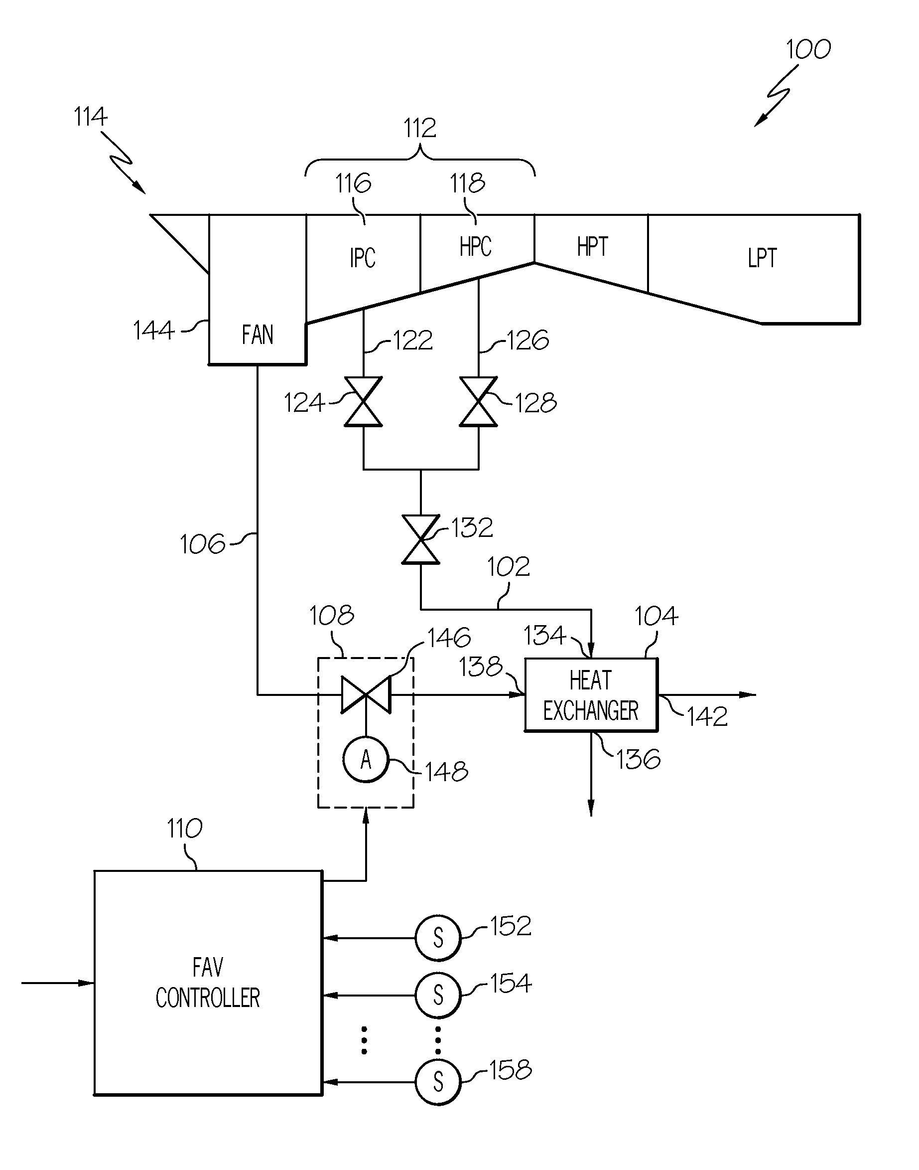
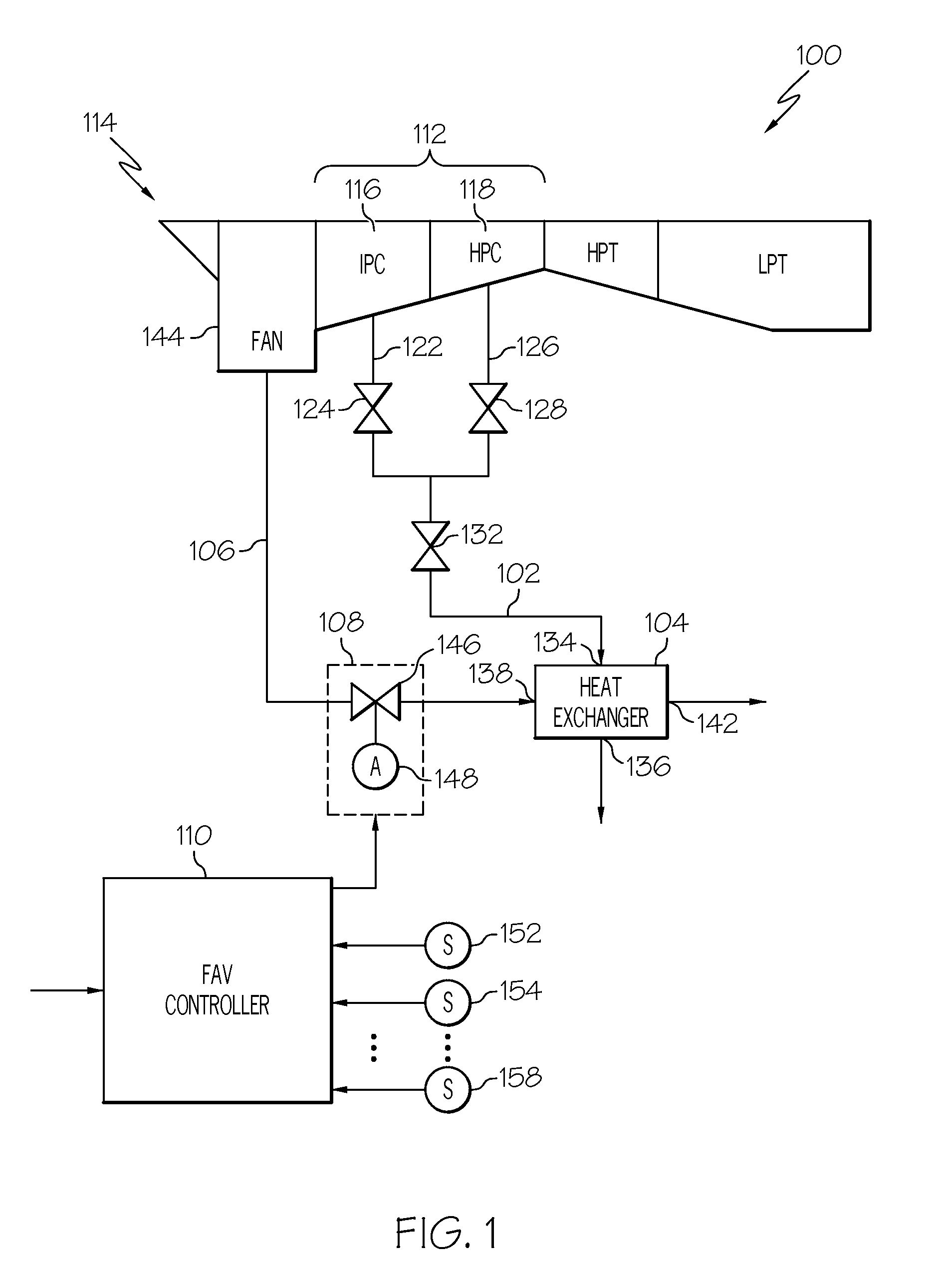
[0019]Turning now to FIG. 1, a schematic diagram of at least a portion of an exemplary gas turbine engine bleed air system 100 is depicted and includes a bleed air conduit 102, a heat exchanger 104, a fan air conduit 106, a fan air valve (FAV) 108, and a FAV controller 110. The bleed air conduit 102 is coupled to receive compressed air from the compressor section 112 of a gas turbine engine 114. It will be appreciated that the engine bleed air system 100 may be configured such that the bleed air conduit 102 may receive compressed air from one or more compressors in the engine compressor section 112. For example, in the depicted embodiment the engine bleed air system 100 is configured such th...


PUM


Abstract

A system and method are provided for controlling the temperature of engine bleed air from a turbofan gas turbine engine. The system includes a fan air valve and a fan air valve controller. The fan air valve is adapted to receive a flow of fan air from a turbofan gas turbine engine intake fan. The fan air valve is coupled to receive valve position commands and is configured, in response to the valve position commands, to move to a valve position to thereby control the engine bleed air temperature. The fan air valve controller is configured to implement a linear quadratic regulator (LQR) control. The fan air valve controller is adapted to receive a plurality of sensor signals, each sensor signal representative of one or more system parameters, and is configured, in response to the sensor signals, to supply the valve position commands to the fan air valve.

Description

PRIORITY CLAIM[0001]This application claims the benefit of U.S. Provisional Application No. 61 / 148,590, filed Jan. 30, 2009.TECHNICAL FIELD[0002]The present invention generally relates to valve control and, more particularly, to a linear quadratic regulator control scheme for an aircraft engine bleed air temperature control system.BACKGROUND[0003]A gas turbine engine may be used to supply power to various types of vehicles and systems. For example, gas turbine engines may be used to supply propulsion power to an aircraft. Many gas turbine engines include at an intake section, a compressor section, a combustor section, and a turbine section. The intake section includes a fan, which draws air into the engine and accelerates it. A fraction of the accelerated air exhausted from the fan is directed through an engine bypass section disposed between a fan case and an engine cowl, and provides a forward thrust.[0004]The compressor section, which may include two or more compressor stages, re...

Claims


Application Information

Patent Timeline
Patent Type & Authority Patents(United States)
IPC IPC(8): F04D27/00F01B25/10F02K3/06
CPCF02C6/08F02C7/14Y02T50/675F05D2270/303Y02T50/60
Inventor BROWN, RYANOLIVAREZ, JASONROBERTS, KENNETH
Owner HONEYWELL INT INC
Why Eureka
Try Eureka