
Adjustable thermal cap

a heat transfer cap and adjustable technology, applied in the field of tissue region cooling methods and apparatuses, can solve the problems of reducing the effectiveness of heat transfer between the patient's scalp and the cap, reducing the efficiency of heat transfer, and reducing the risk of ischemic injury in patients

Inactive Publication Date: 2013-09-10
MEDCOOL
View PDF183 Cites 24 Cited by
  • Summary
  • Abstract
  • Description
  • Claims
  • Application Information

AI Technical Summary

Problems solved by technology

Patients that suffer from stroke, cardiac arrest, or head trauma, as well as patients that have undergone invasive brain or vascular surgery, are at risk for ischemic injury which can occur when an organ does not receive a sufficient supply of oxygen.
As a result, the patient can experience a critical rise in intra-cranial pressure, brain cell death, and a loss of brain function.
However, the presence of hair and / or air pockets between the scalp of the patient and the liner walls can act as a thermal insulator and can minimize the effectiveness of the heat transfer between the patient's scalp and the cap.

Method used


Image

  • Adjustable thermal cap
  • Adjustable thermal cap
  • Adjustable thermal cap

Examples


Embodiment Construction

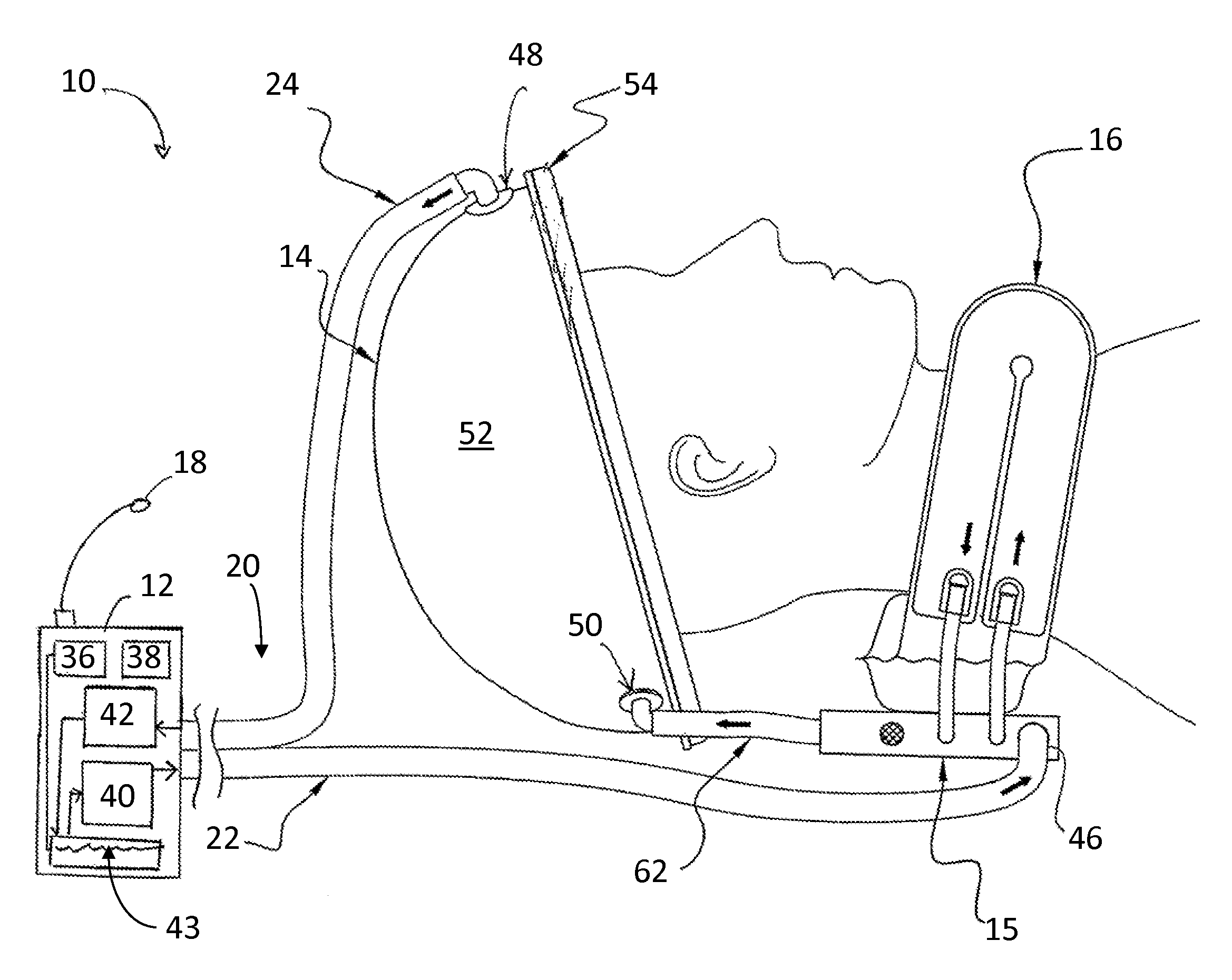
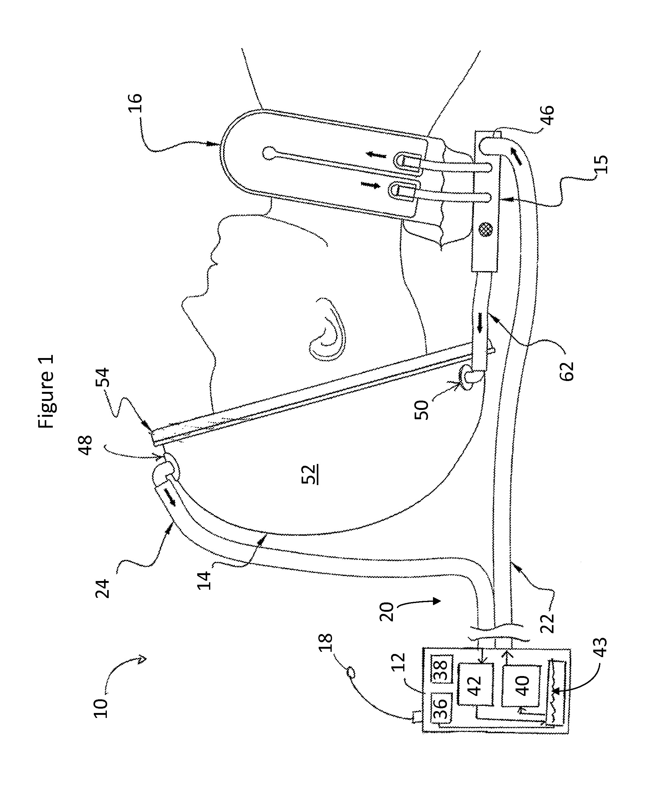
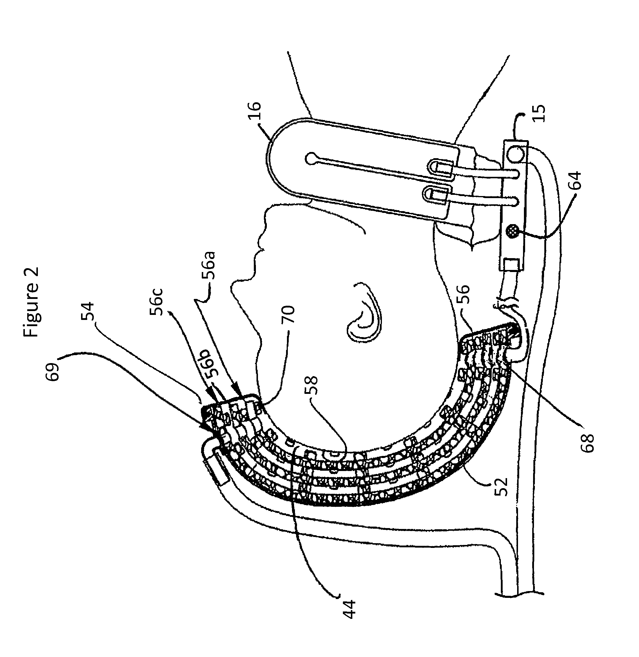
[0045]The present invention relates to a “one size fits all” thermal cap that can fit a variety of head sizes. The cap includes a shell having a fluid inlet and outlet, removable sizing layers disposed within the shell, and an elastomeric member disposed about the periphery of the shell. Depending upon the size of a patient's head, sizing layers can either be added to or removed from the outer shell (e.g., for smaller or larger heads, respectively) to maintain a fluid circulation space between the head and the rigid shell and allow substantially even distribution of a thermal fluid about the scalp of the patient during operation. The elastomeric member can seal the periphery of the cap to the patient's head and prevent leakage of the thermal fluid from the cap. General features of thermal devices for heating and cooling the head of a subject are revealed in pending a U.S. patent application bearing Ser. No. 11 / 284,114, filed Nov. 21, 2005 entitled “Method and Device for Rapidly Indu...


PUM


Abstract

A thermal cap that can fit a variety of head sizes is disclosed. The cap can include a shell having a fluid inlet and outlet, a sealing mechanism and removable sizing layers disposed within the shell. Depending upon the size of a patient's head, sizing layers can either be added to or removed from the outer shell to maintain a fluid circulation space between the head and the rigid shell and allow substantially even distribution of a thermal fluid about the scalp of the patient during operation. The shell is preferably rigid and an elastomeric member can seal the periphery of the cap to the patient's head to prevent leakage. Other types and aspects of thermal cap systems are also disclosed.

Description

CROSS REFERENCE TO RELATED APPLICATIONS[0001]The present application claims the benefit of a U.S. Provisional Patent Application bearing Ser. No. 60 / 852,600, filed Oct. 18, 2006, entitled “Adjustable Cooling Cap.” The entire contents of the provisional patent application are hereby incorporated by reference herein.[0002]The present application is related to a copending PCT International Patent Application, bearing International Application No. PCT / U.S.2006 / 012561 and having International Filing Date Apr. 3, 2006; which claims the benefit of U.S. Provisional Patent Application Ser. No. 60 / 669,336, filed Apr. 7, 2005. These applications are hereby incorporated herein by reference in their entirety.FIELD OF THE APPLICATION[0003]The present application generally relates to a method and apparatus for heat transfer with a patient, and more particularly to a method and apparatus for cooling a tissue region of interest.BACKGROUND OF THE APPLICATION[0004]Patients that suffer from stroke, car...

Claims


Application Information

Patent Timeline
Patent Type & Authority Patents(United States)
IPC IPC(8): A61F7/00
CPCA61F7/10A61F2007/0008A61F2007/0056
Inventor RADZIUNAS, JEFFREYLENNOX, CHARLES D.
Owner MEDCOOL
Learn More