System and method for head size equalization in 360 degree panoramic images

a technology of head size and panoramic image, applied in the field of viewing images using a computer, to achieve the effect of preserving the context of the room and minimizing the introduction of new distortions

Inactive Publication Date: 2007-02-27
MICROSOFT TECH LICENSING LLC
View PDF66 Cites 24 Cited by
  • Summary
  • Abstract
  • Description
  • Claims
  • Application Information

AI Technical Summary

Benefits of technology

[0013]The real-time panoramic image correction system and method provides head size normalization, making far away objects, such as heads, appear closer and therefore larger. Close heads, which are big, are also made smaller. As a result people on the far end of a table are larger and are viewable even on 1024×166 pixel displays. In one embodiment the system and method of the invention, a user also selects the conference table shape and size and the real-time panoramic image correction system modifies the panoramic image stitching table to match the meeting table so that the head sizes of meeting participants are normalized at the same time the stitching is computed.
[0016]In another embodiment of the invention, the warp table is concatenated with the stitching table in order to improve computational efficiency and allow for the normalization of head sizes while the input images are being stitched into the panoramic image. In this embodiment, a set of images are stitched into an imaginary stitched panoramic image using a stitching table. Besides the set images, horizontal feature parameters are also input. The imaginary panoramic image is used to compute the warp table, which is then concatenated with the stitching table. This concatenated warping and stitching table is then used to stitch the set of input images into an actual, distortion corrected panorama.

Problems solved by technology

However, the previous patent application used this technique only for up to 180 degree images.

Method used


Image

  • System and method for head size equalization in 360 degree panoramic images
  • System and method for head size equalization in 360 degree panoramic images
  • System and method for head size equalization in 360 degree panoramic images

Examples


Embodiment Construction

[0038]In the following description of the invention, reference is made to the accompanying drawings, which form a part thereof, and in which is shown by way of illustration a specific example whereby the invention may be practiced. It is to be understood that other embodiments may be utilized and structural changes may be made without departing from the scope of the present invention.

1.0 General Overview

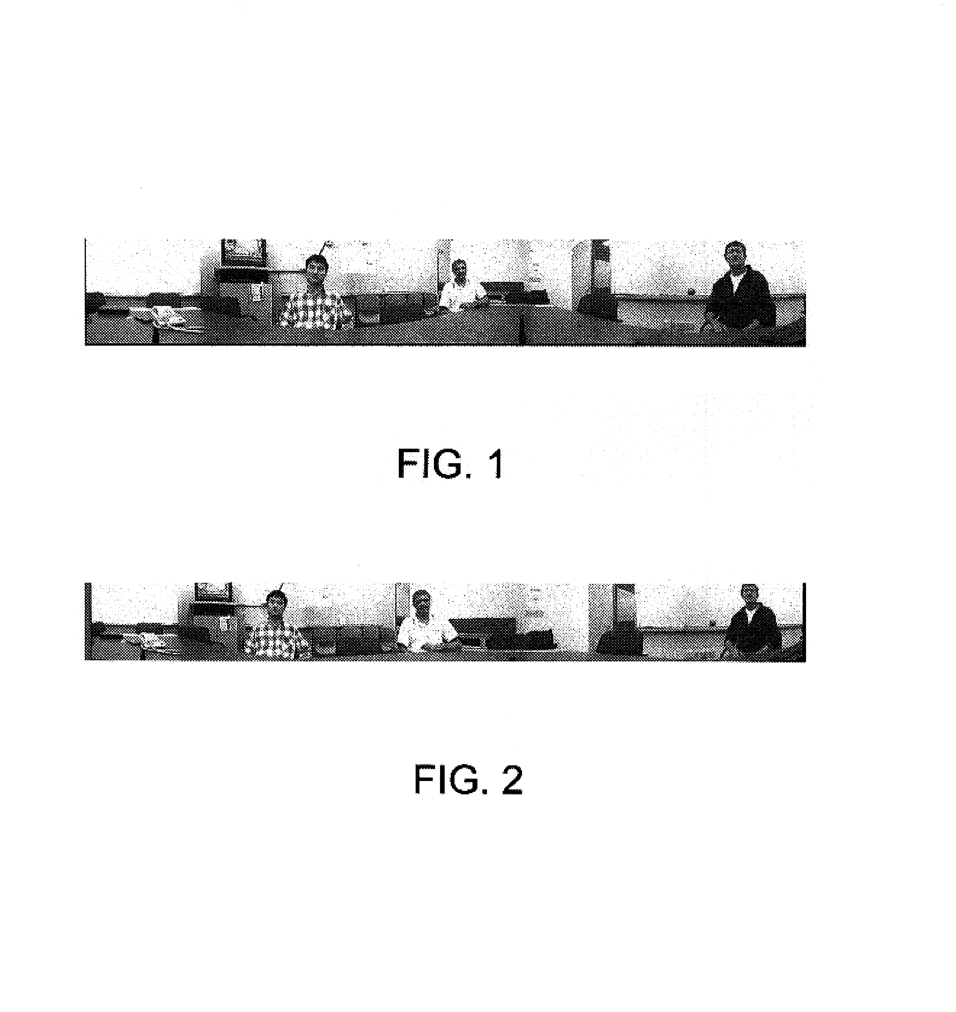
[0039]FIG. 1 shows an image taken by a 360 degree omni-directional camera sitting in the middle of a table in a meeting room. This camera configuration is typical of what one might use in a video conferencing application. Referring to FIG. 1, one can see that the person in white appears much smaller than the other two people. The reason for this is that he sits further away from the camera. First of all, the person in white is much less visible and appears far away from the viewer thus affecting the experience of real time communication. Second, the image size is usually limited due ...


PUM


Abstract

A real-time approximately 360 degree image correction system and a method for alleviating distortion and perception problems in images captured by omni-directional cameras. In general, the real-time panoramic image correction method generates a warp table from pixel coordinates of a panoramic image and applies the warp table to the panoramic image to create a corrected panoramic image. The corrections are performed using a parametric class of warping functions that include Spatially Varying Uniform (SVU) scaling functions. The SVU scaling functions and scaling factors are used to perform vertical scaling and horizontal scaling on the panoramic image pixel coordinates. A horizontal distortion correction is performed using the SVU scaling functions at at least two different scaling factors. This processing generates a warp table that can be applied to the panoramic image to yield the corrected panoramic image. In one embodiment the warp table is concatenated with a stitching table used to create the panoramic image.

Description

[0001]This is a continuation-in-part of application Ser. No. 10 / 186,915 filed Jun. 28, 2002 and entitled “REAL-TIME WIDE-ANGLE IMAGE CORRECTION SYSTEM AND METHOD FOR COMPUTER IMAGE VIEWING”.TECHNICAL FIELD[0002]The present invention relates in general to viewing images using a computer, and more particularly to a system and a method for real-time correction of panoramic images captured by an omni-directional camera to alleviate distortion and perception problems associated with such images.BACKGROUND OF THE INVENTION[0003]Wide-angle cameras, typically having a field of view greater than 60 degrees, often are used to capture large scenes. A wide-angle image taken by a wide-angle camera can be viewed using at least two types of projections. Linear perspective and cylindrical projections are the most typical projections used to view wide-angle images.[0004]A linear perspective projection is an image captured by a wide-angle lens that is projected onto a flat piece of film. Linear persp...

Claims


Application Information

Patent Timeline
Patent Type & Authority Patents(United States)
IPC IPC(8): G06K9/36G09G5/00H04N7/00H04N5/262G06K9/00G06T3/00G06T5/00H04N7/18
CPCG06K9/00228G06T3/0062G06T7/0024G06T5/006G06T3/4038G06T7/30G06V40/161G06T3/00G06T5/00G06V10/20
Inventor LIU, ZICHENGCUTLER, ROSSCOHEN, MICHAELZHANG, ZHENGYOU
Owner MICROSOFT TECH LICENSING LLC
Why Eureka
Try Eureka