
Multi-rate implementation without high-pass filter

a multi-rate implementation and high-pass filter technology, applied in the field of digital signal filtering, can solve problems such as constant group delay, and achieve the effect of reducing computational requirements and eliminating high-pass filtering

Active Publication Date: 2013-09-17
AUDYSSEY LABORATORIES
View PDF15 Cites 27 Cited by
  • Summary
  • Abstract
  • Description
  • Claims
  • Application Information

AI Technical Summary

Benefits of technology

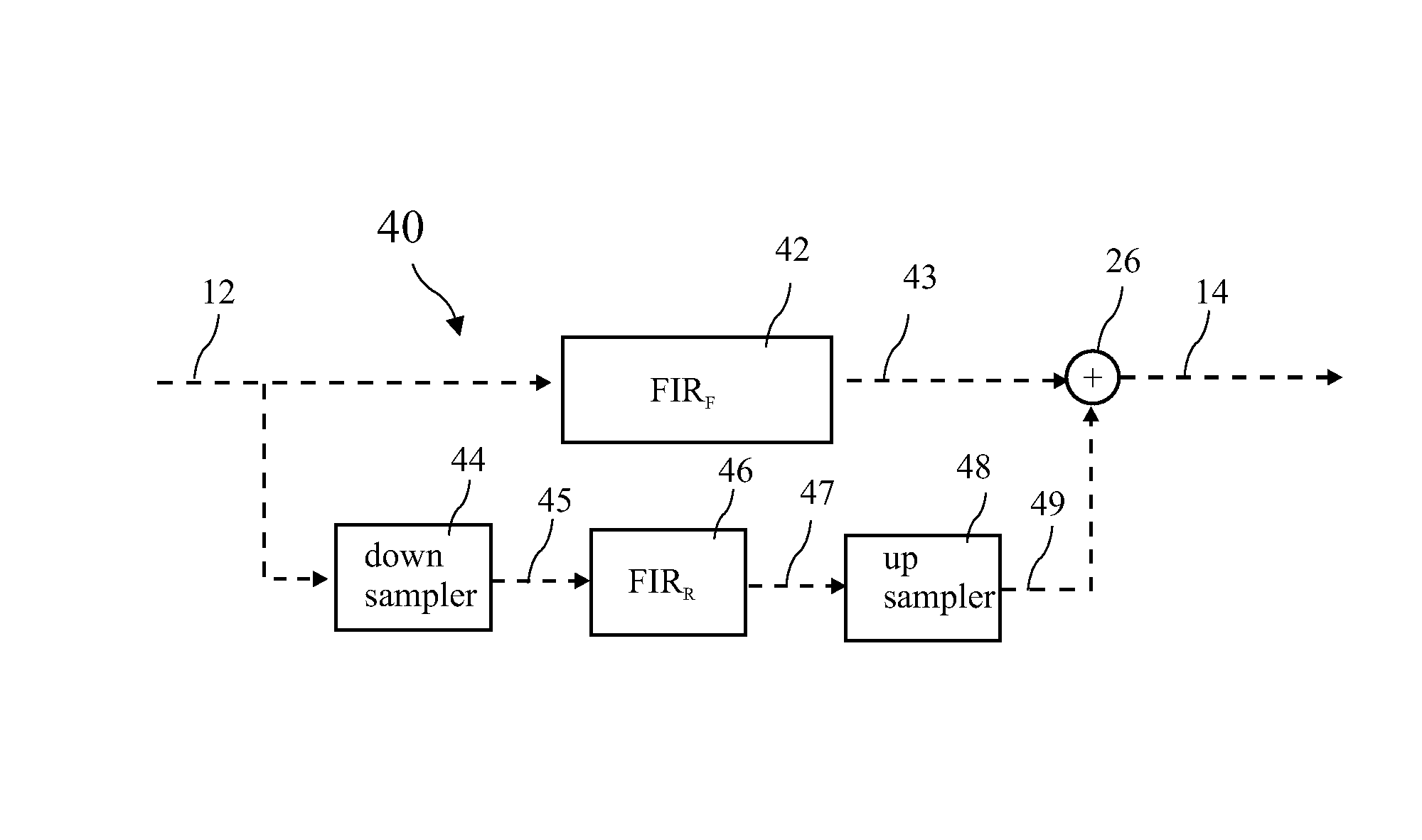
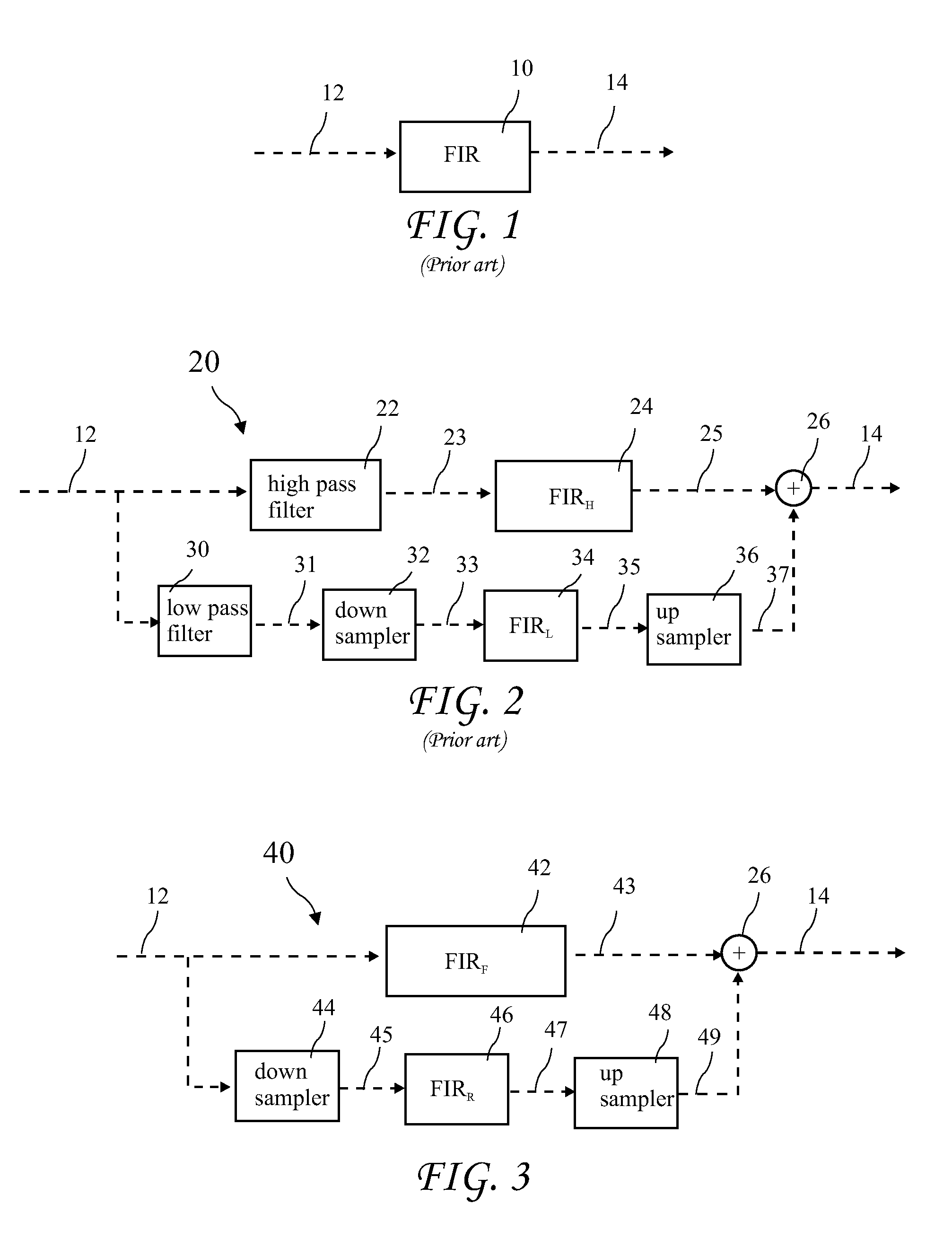
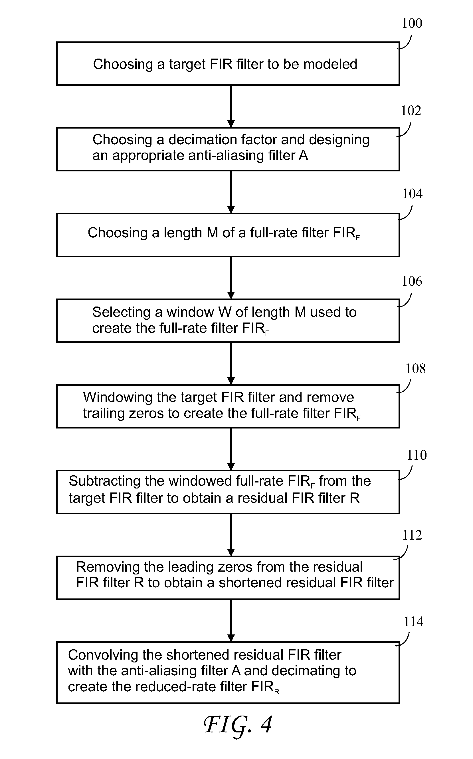
[0004]The present invention addresses the above and other needs by providing a filtering method which approximates a target Finite Impulse Response (FIR) (or transversal) filter and reduces computational requirements by eliminating high pass filtering required by known multi-rate filters. An input signal is copied into two identical signals and processed in parallel by a full-rate path, and by a reduced-rate path. Parallel filters are computed and applied in each path, the reduced-rate signal is up-sampled, and the two signals summed. The high pass filter required by known multi-rate filters is eliminated and the low pass filter in the prior art is implicit in a down sampling. Linear phase FIR filters are used for down and up sampling, resulting in constant group delay. Added benefits include the option of zero added latency through the filtering and the constant group delay added to the target FIR filter. The user may choose criteria such as minimum resolution in each band.
[0005]In accordance with one aspect of the invention, there is provided a method of calculating a pair of FIR filters, and a corresponding signal processing diagram for applying the calculated filters. The filters are derived to eliminate the need for a separate high pass filter required by known multi-rate filters.

Problems solved by technology

Linear phase FIR filters are used for down and up sampling, resulting in constant group delay.

Method used


Image

  • Multi-rate implementation without high-pass filter
  • Multi-rate implementation without high-pass filter
  • Multi-rate implementation without high-pass filter

Examples


Embodiment Construction

[0032]The following description is of the best mode presently contemplated for carrying out the invention. This description is not to be taken in a limiting sense, but is made merely for the purpose of describing one or more preferred embodiments of the invention. The scope of the invention should be determined with reference to the claims.

[0033]A prior art digital filter with a single Finite Impulse Response (FIR) filter (the target FIR filter) 10 applied to an input signal 12 to produce a filtered signal 14. The Target FIR filter 10 must perform operations at the high sample rate of the input signal 12 and also be of sufficient length to provide accurate filtering to low frequency components in the input signal. The resulting processing may require a very large number of operations at the high sample rate.

[0034]A prior art multi-rate digital filter 20 with two parallel FIR filters, FIRH 24 and FIRL 34, applied to the input signal 12 is shown in FIG. 2. The input signal 12 is proce...


PUM


Abstract

A filtering method approximates a target Finite Impulse Response (FIR) (or transversal) filter and reduces computational requirements by eliminating high pass filtering required by known multi-rate filters. An input signal is copied into two identical signals and processed in parallel by a full-rate path, and by a reduced-rate path. Parallel filters are computed and applied in each path, the reduced-rate signal is up-sampled, and the two signals summed. The high pass filter required by known multi-rate filters is eliminated and the low pass filter in the prior art is implicit in a down sampling. Linear phase FIR filters are used for down and up sampling, resulting in constant group delay. Added benefits include the option of zero added latency through the filtering and the constant group delay added to the target FIR. The user may choose criteria such as minimum resolution in each band.

Description

BACKGROUND OF THE INVENTION[0001]The field of the invention is digital signal filtering and in particular methods to improve low frequency resolution without increasing processing requirements.[0002]Broadband digital signals often require filtering for their intended use. For example, in audio systems, signals may be filtered (often referred to as equalizing) to compensate for characteristics of speakers and the listening environment. Such digital signals must be at a sufficiently high sample rate to carry the high frequency signal components. Finite Impulse Response (FIR) (or transversal) filters are preferred in many applications to maintain linear phase or minimum phase for accurate sound reproduction. In order to filter such signals using a single FIR filter, the filtering must be performed at the high sample rate of the digital signal, and to achieve high resolution filtering for low frequencies present in the signal, a very long FIR filter is also required. In some audio syste...

Claims


Application Information

Patent Timeline
Patent Type & Authority Patents(United States)
IPC IPC(8): G06F17/10
CPCH03H17/0223H03H17/0283H03H17/06
Inventor CLARK, JEFFREY
Owner AUDYSSEY LABORATORIES
Learn More