Structure based fluid distribution system

a fluid distribution system and structure technology, applied in the field of climate control, can solve the problems of seat occupants' back and other pressure points being sweaty, hot and uncomfortable for a long time, and problems that have been experienced with existing climate control systems

Active Publication Date: 2013-09-24
GENTHERM INC
View PDF210 Cites 67 Cited by
  • Summary
  • Abstract
  • Description
  • Claims
  • Application Information

AI Technical Summary

Problems solved by technology

For example, an automotive vehicle exposed to the summer weather, where the vehicle has been parked in an unshaded area for a long period of time, can cause the vehicle seat to be very hot and uncomfortable for the occupant for some time after entering and using the vehicle, even with normal air conditioning.
Furthermore, even with normal air-conditioning, on a hot day, the seat occupant's back and other pressure points may remain sweaty while seated.
There are, however, problems that have been experienced with existing climate control systems for seat assemblies.
This can compromise the comfort and / or the appearance of the seat.

Method used


Image

  • Structure based fluid distribution system
  • Structure based fluid distribution system
  • Structure based fluid distribution system

Examples


Embodiment Construction

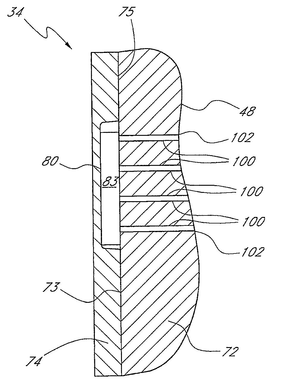
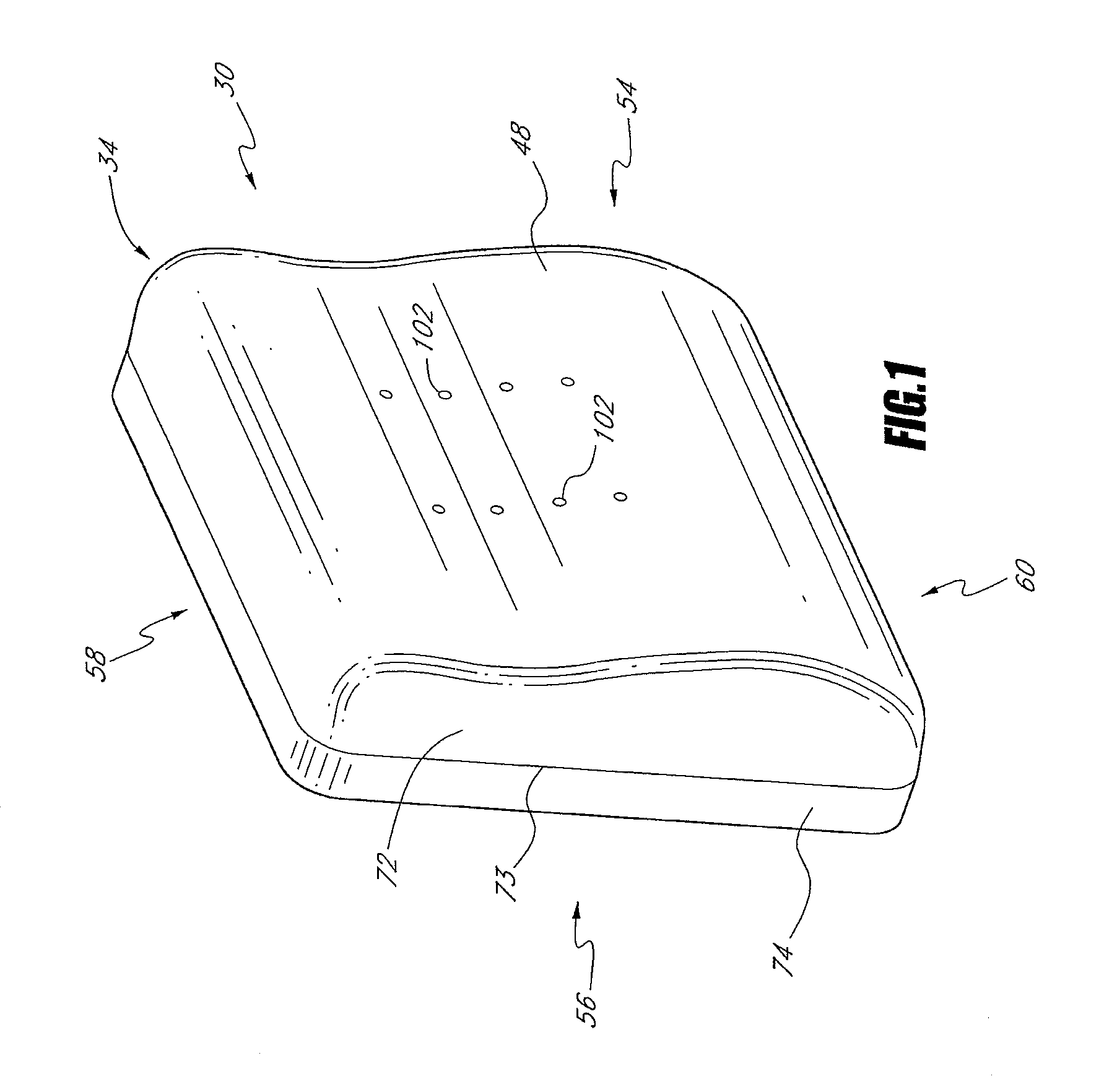
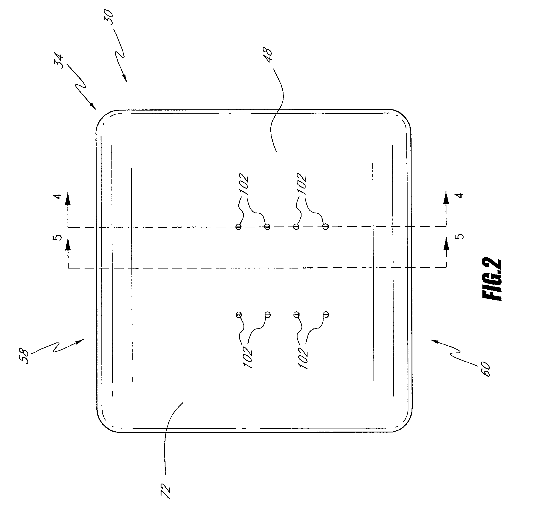
[0033]FIGS. 1 and 2 are front perspective and front views of an embodiment of a climate controlled seat assembly 30. As shown, the seat assembly 30 comprises a backrest 34, which can be coupled and / or used in combination with a seat portion (not shown) to form a seat. The seat assembly 30 also includes a climate control system 36, which will be described in more detail below with reference to FIGS. 3-6.

[0034]When an occupant sits in the seat assembly 30, the occupant's seat is located on the seat portion and the occupant's back contacts a front surface 48 of the backrest portion 34. The backrest 34 and the seat portion cooperate to support the occupant in a sitting position. The seat assembly 30 can be configured and sized to accommodate occupants of various size and weight.

[0035]In the illustrated embodiment, the seat assembly 30 is similar to a standard automotive seat. However, it should be appreciated that certain features and aspects of the seat assembly 30 described herein may...


PUM


Abstract

A climate controlled seat assembly includes a seat cushion that has an outer surface with a first side for supporting an occupant in a seated position and a second side, which generally faces in an opposite direction than the first side. An air passage extends from the first side to the second side of the seat cushion. A support member has a first side that is configured to provide support to the seat cushion and a second side. the first side and the second side of the support member generally face in opposite directions. A distribution passage is in communication with the air passage and is formed at least in part by a recess formed at least in part in one of the first side of the support member and the second side of the seat cushion.

Description

PRIORITY INFORMATION[0001]This application claims priority to U.S. Provisional Patent Application No. 60 / 809,459, filed May 31, 2006, the entirety of which is hereby incorporated by reference herein.INCORPORATION BY REFERENCE[0002]The entirety of U.S. Provisional Patent Application No. 60 / 809,459, filed May 31, 2006, is expressly incorporated by reference herein and made a part of the present specification.BACKGROUND OF THE INVENTION[0003]1. Field of the Invention[0004]This invention relates to climate control. More specifically, this invention relates to climate control of a seat.[0005]2. Description of the Related Art[0006]Temperature modified air for environmental control of living or working space is typically provided to relatively extensive areas, such as entire buildings, selected offices, or suites of rooms within a building. In the case of vehicles, such as automobiles, the entire vehicle is typically cooled or heated as a unit. There are many situations, however, in which ...

Claims


Application Information

Patent Timeline
Patent Type & Authority Patents(United States)
IPC IPC(8): A47C16/00
CPCA47C7/74
Inventor TERECH, JOHNMARQUETTE, DAVID
Owner GENTHERM INC
Why Eureka
Try Eureka