Cable connector and antenna component

a technology of cable connectors and antenna components, applied in the direction of antenna connectors, radiating element structural forms, coupling device connections, etc., can solve the problems of high manufacturing cost, difficult to make thin (low-profile), and complicated assembly skills, so as to simplify the assembly steps and simplify the installation. the effect of the wiring board and the reduction of the manufacturing cost of the cable connector

Inactive Publication Date: 2013-09-24
THE FUJIKURA CABLE WORKS LTD
View PDF12 Cites 3 Cited by
  • Summary
  • Abstract
  • Description
  • Claims
  • Application Information

AI Technical Summary

Benefits of technology

[0021]Furthermore, the plug connector can be installed on the wiring board with ease, which makes it possible to simplify the assembly steps. As a result, the manufacturing cost of the cable connector can be reduced. Furthermore, because the assembly steps can be simplified, the manufactured cable connectors are unlikely to suffer from performance variations, making it possible to provide stable products.
[0022]In addition, with the change such as in width and length of the signal transmission line, in a gap between the signal transmission line and the second conductor, and in thickness of the first conductor and the second conductor, it is possible to control the characteristic impedance of the signal transmission line with ease. Therefore, impedance of the wiring board can be optimized with ease in accordance with the communication characteristics (frequency band, communication distance, and the like) at high frequencies of the equipment and the antenna that are to be connected with the cable connector.
[0024]Furthermore, the plug connector can be installed on the first wiring board with ease, which makes it possible to simplify the assembly steps. As a result, the manufacturing cost of the antenna component can be reduced. Furthermore, because the assembly steps can be simplified, the manufactured antenna components are unlikely to suffer from performance variations, making it possible to provide stable products.
[0025]In addition, with the change in width and length of the signal transmission line, in a gap between the signal transmission line and the second conductor, and in thickness of the first conductor and the second conductor, it is possible to control the characteristic impedance of the signal transmission line. Therefore, impedance of the first wiring board can be optimized with ease in accordance with the communication characteristics (frequency band, communication distance, and the like) at high frequencies of the antenna of the second wiring board.

Problems solved by technology

In addition, the assembly requires a sophisticated skill.
Furthermore, because the coaxial cable has a large diameter, it is difficult to make thin (low-profile) the connection portion (the connector connection portion) between the coaxial cable and the RF connector (that is, make thin the assembly 120 shown in FIG. 12D).
Furthermore, with numerous steps for assembling the RF connector with the coaxial cable, their manufacturing cost becomes high.

Method used


Image

  • Cable connector and antenna component
  • Cable connector and antenna component
  • Cable connector and antenna component

Examples


third embodiment

[0090]FIGS. 5A to 5D are schematic diagrams showing a third embodiment of the cable connector according to the present invention. FIG. 5A is a perspective view of the present embodiment. FIG. 5B is a plan view of the present embodiment. FIG. 5C is a cross-sectional view of FIG. 5B, taken along the A-A line. FIG. 5D is a cross-sectional view of FIG. 5B, taken along the B-B line.

[0091]In FIGS. 5A to 5D, like constituent parts to those of the aforementioned first embodiment are designated with same reference numerals and are not repetitiously explained.

[0092]A cable connector 1C (1) of the present embodiment is different from the aforementioned cable connector 1A (1) of the first embodiment in that a wiring board 10B (10) comprises a first conductor 13, a second conductor 14, and a third conductor 17 laminated in this order respectively via an insulating material 15. The first conductor 13, the second conductor 14, and the third conductor 17 are electrically connected via through-holes...

fourth embodiment

[0105]FIG. 8 is a perspective view showing a fourth embodiment of the cable connector according to the present invention.

[0106]A cable connector 1D (1) of the present embodiment is different from the aforementioned cable connector 1C (1) of the third embodiment in that a coaxial cable 41, which is electrically connected with a signal transmission line 16, is disposed on one surface of the third conductor 17 at one end portion of the wiring board 10B.

[0107]As the coaxial cable 41, one similar to that used in the second embodiment can be used. Also in the present embodiment, a central conductor 42 of the coaxial cable 41 is electrically connected with the signal transmission line 16 via a conducting member 46, and an external conductor 44 of the coaxial cable 41 is electrically connected with the third conductor 17. In the present embodiment, there is placed a conducting member 46 in a through-hole that penetrates the third conductor 17 and the insulating material 15 placed between th...

first embodiment

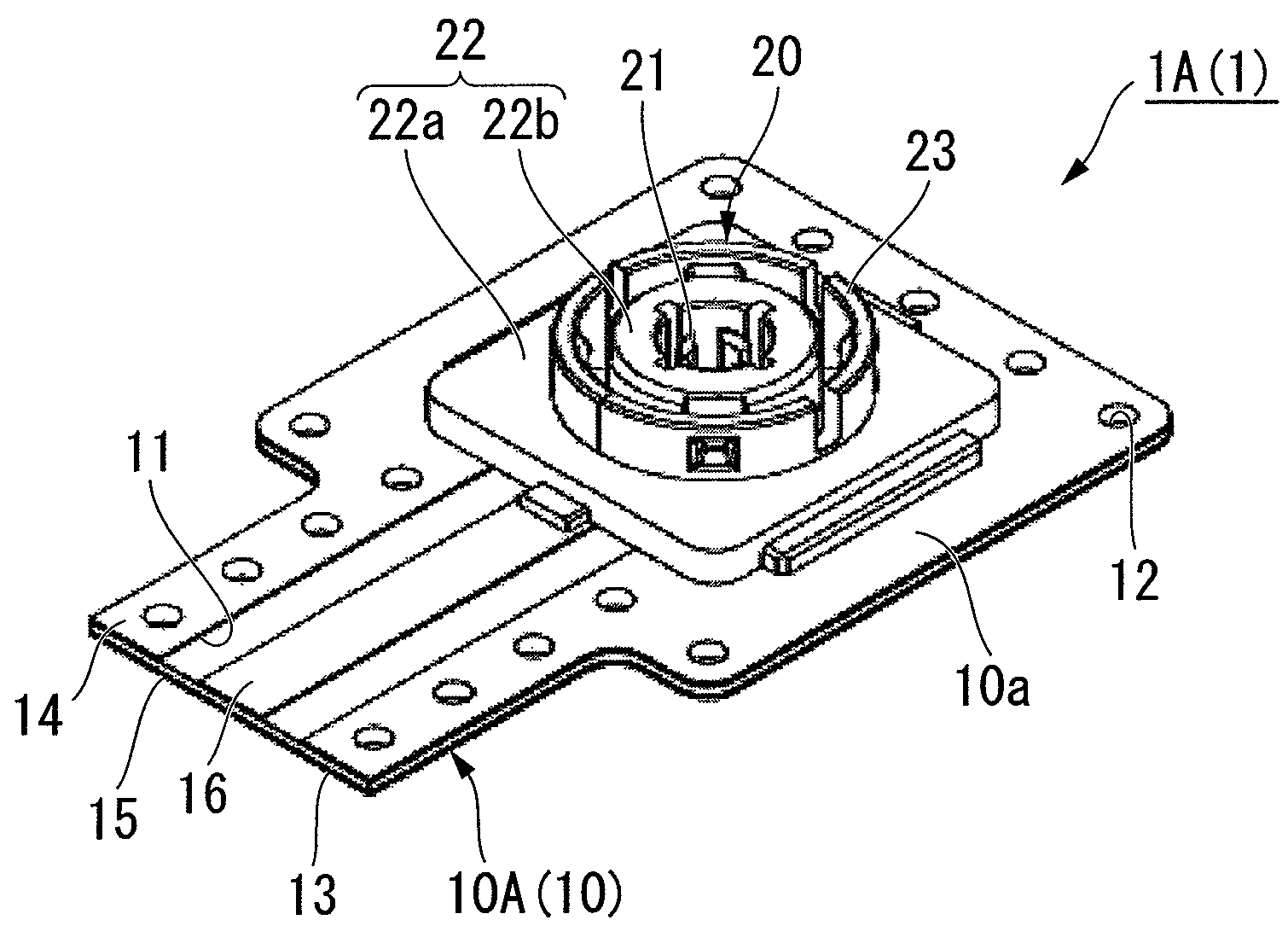
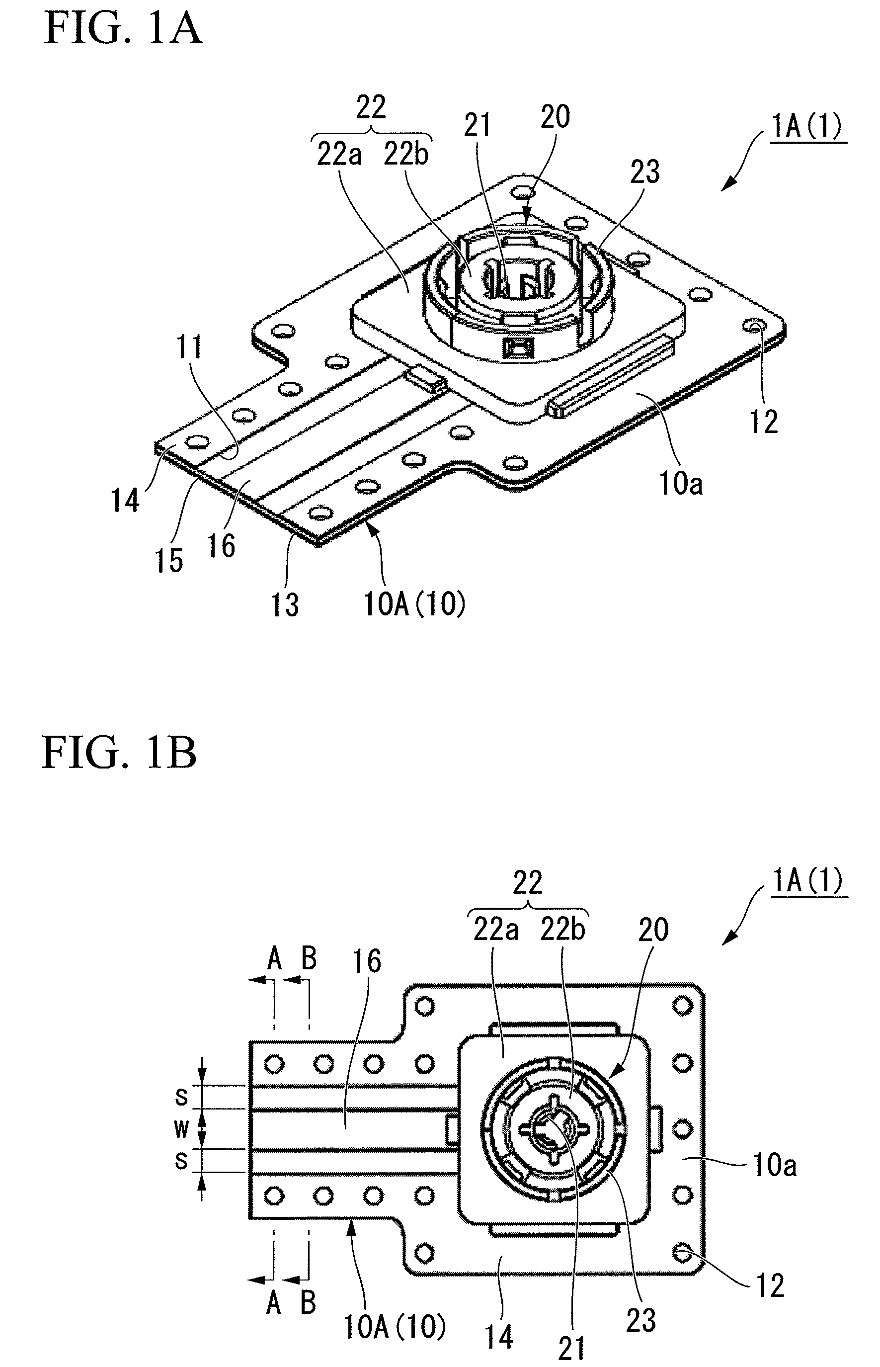
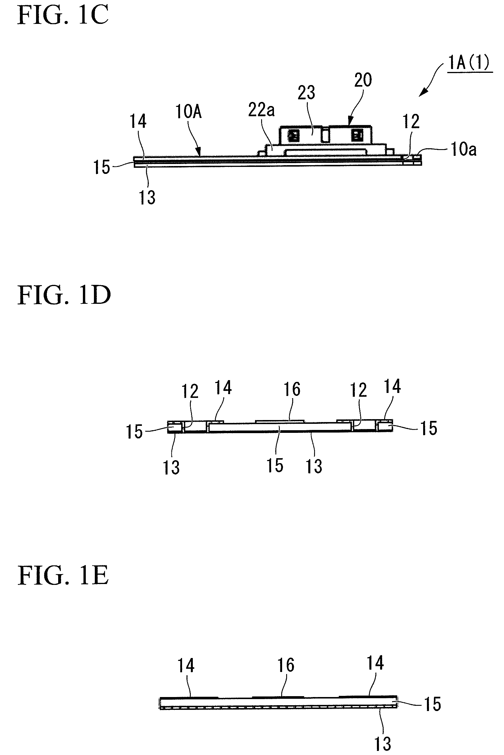
[0112]FIG. 9 is a schematic perspective view showing a first embodiment of an antenna component according to the present invention and how it is used.

[0113]An antenna component 50A (50) of the present embodiment comprises: the aforementioned cable connector 1A (the wiring board 10A and the plug connector 20) of the first embodiment; and a second wiring board 60A (60). Hereinafter, the wiring board 10A of the cable connector 1A is sometimes referred to as the first wiring board 10A.

[0114]The second wiring board 60 is coupled to the first wiring board 10A. On the second wiring board 60A, there is provided an antenna 65A (65) that is electrically connected with the signal transmission line 16 of the first wiring board 10A.

[0115]As for a plurality of through-holes 12 provided along the edge portion of the first wiring board 10A, a distance d therebetween is set to a length corresponding to ½ or less of the wavelength of the frequency of the antenna 65A.

[0116]The second wiring board 60A ...


PUM


Abstract

Provided is a cable connector of the present invention includes: a wiring board with a signal transmission line; and a plug connector that is provided on one surface of the wiring board and that is electrically connected with the signal transmission line. The wiring board comprises a first conductor, an insulating material, and a second conductor laminated in this order. In a slit formed in the second conductor, the signal transmission line that is a part of the second conductor cut out from the second conductor is arranged at a predetermined distance from the second conductor. The second conductor and the signal transmission line are arranged on the same plane.

Description

CROSS-REFERENCE TO RELATED APPLICATION[0001]This is a Continuation Application of International Application No. PCT / JP2009 / 006942, filed on Dec. 16, 2009, which claims priority to Japanese Patent Application No. 2008-319520, filed on Dec. 16, 2008, and Japanese Patent Application No. 2008-319946, filed on Dec. 16, 2008. The contents of the aforementioned applications are incorporated herein by reference.BACKGROUND OF THE INVENTION[0002]1. Field of the Invention[0003]The present invention relates to a cable connector for connecting an RF module with an antenna in the internal components of electronic equipment, and also relates to an antenna component in which the cable connector is connected with the antenna. More particularly, the present invention relates to a cable connector and an antenna component which eliminate complicated steps of assembling a connector with a transmission line, which are capable of reducing assembly steps in number and a manufacturing cost more than the con...

Claims


Application Information

Patent Timeline
Patent Type & Authority Patents(United States)
IPC IPC(8): H01Q1/50H01R24/38H01R24/86
CPCH01Q1/38H01Q9/0464H01R9/0515H01R2201/02
Inventor TAGUCHI, HIROYUKI
Owner THE FUJIKURA CABLE WORKS LTD
Why Eureka
Try Eureka