Cable connector and antenna component
a technology of cable connectors and antennas, applied in the direction of coupling device connections, contact members penetrating/cutting insulation/cable strands, structural forms of radiating elements, etc., can solve the problems of high manufacturing cost, difficult to make thin (low-profile), and complicated assembly skills, so as to simplify the assembly steps and simplify the effect of installation on the wiring board
- Summary
- Abstract
- Description
- Claims
- Application Information
AI Technical Summary
Benefits of technology
Problems solved by technology
Method used
Image
Examples
third embodiment
[0090]FIGS. 5A to 5D are schematic diagrams showing a third embodiment of the cable connector according to the present invention. FIG. 5A is a perspective view of the present embodiment. FIG. 5B is a plan view of the present embodiment. FIG. 5C is a cross-sectional view of FIG. 5B, taken along the A-A line. FIG. 5D is a cross-sectional view of FIG. 5B, taken along the B-B line.
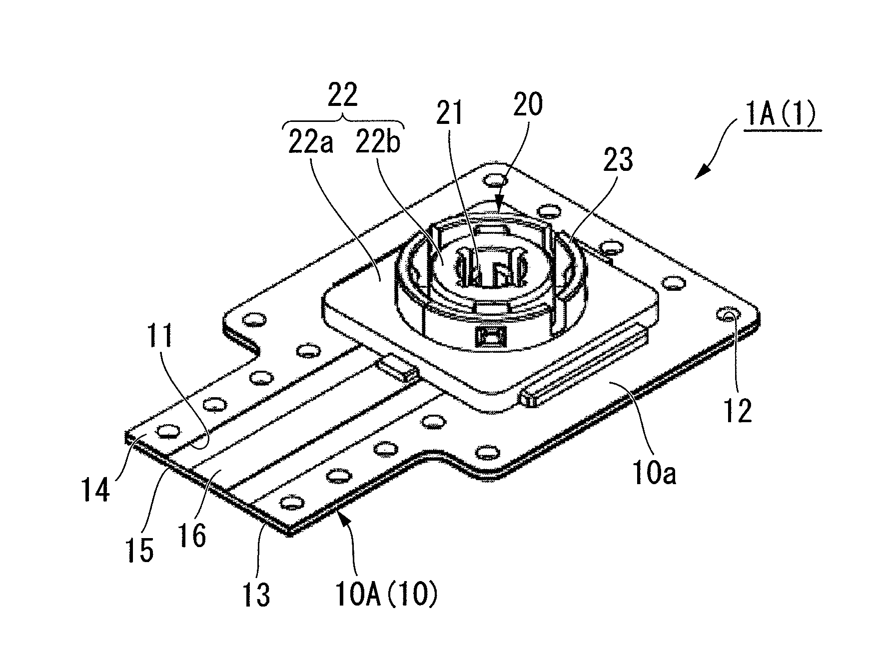
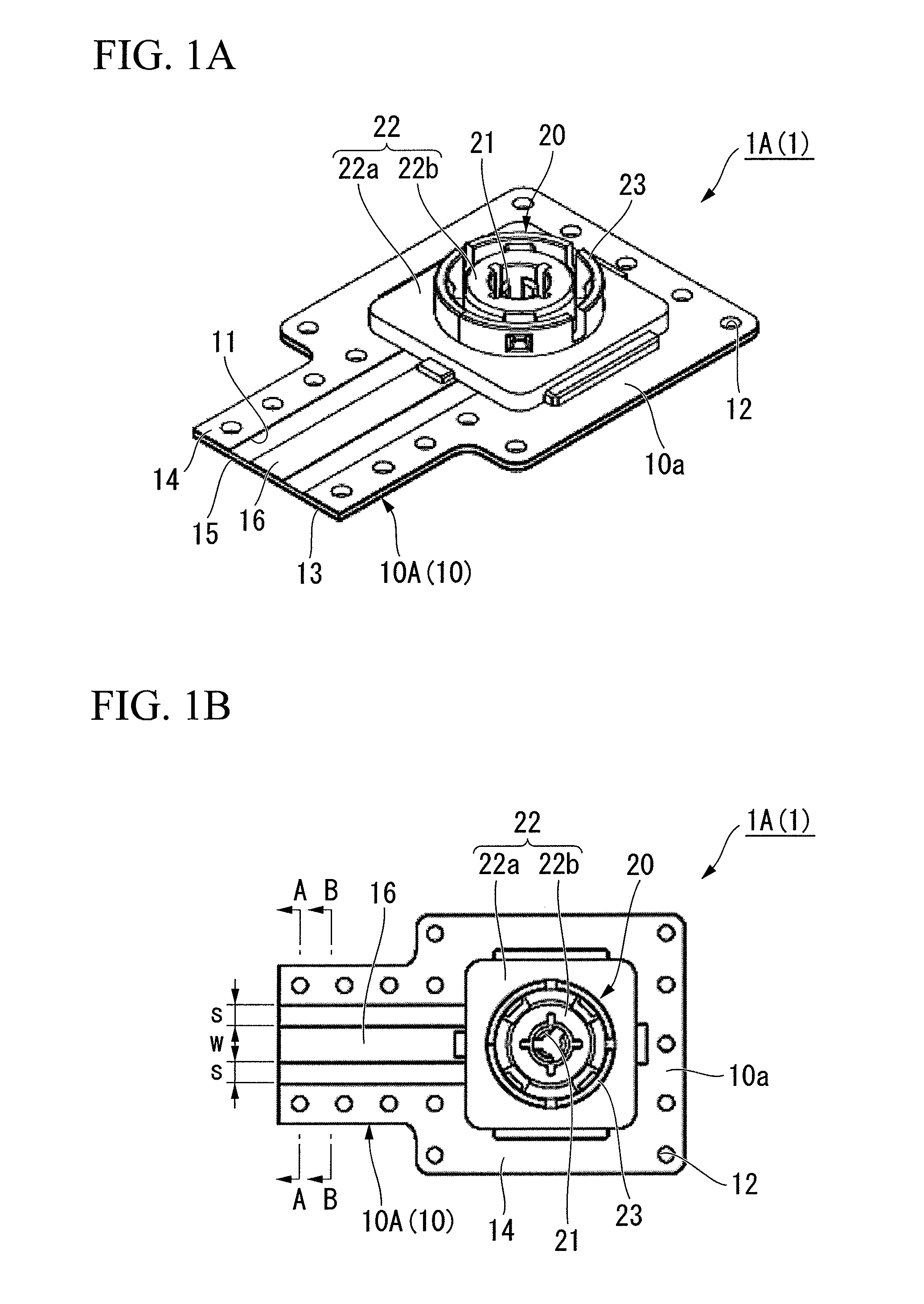
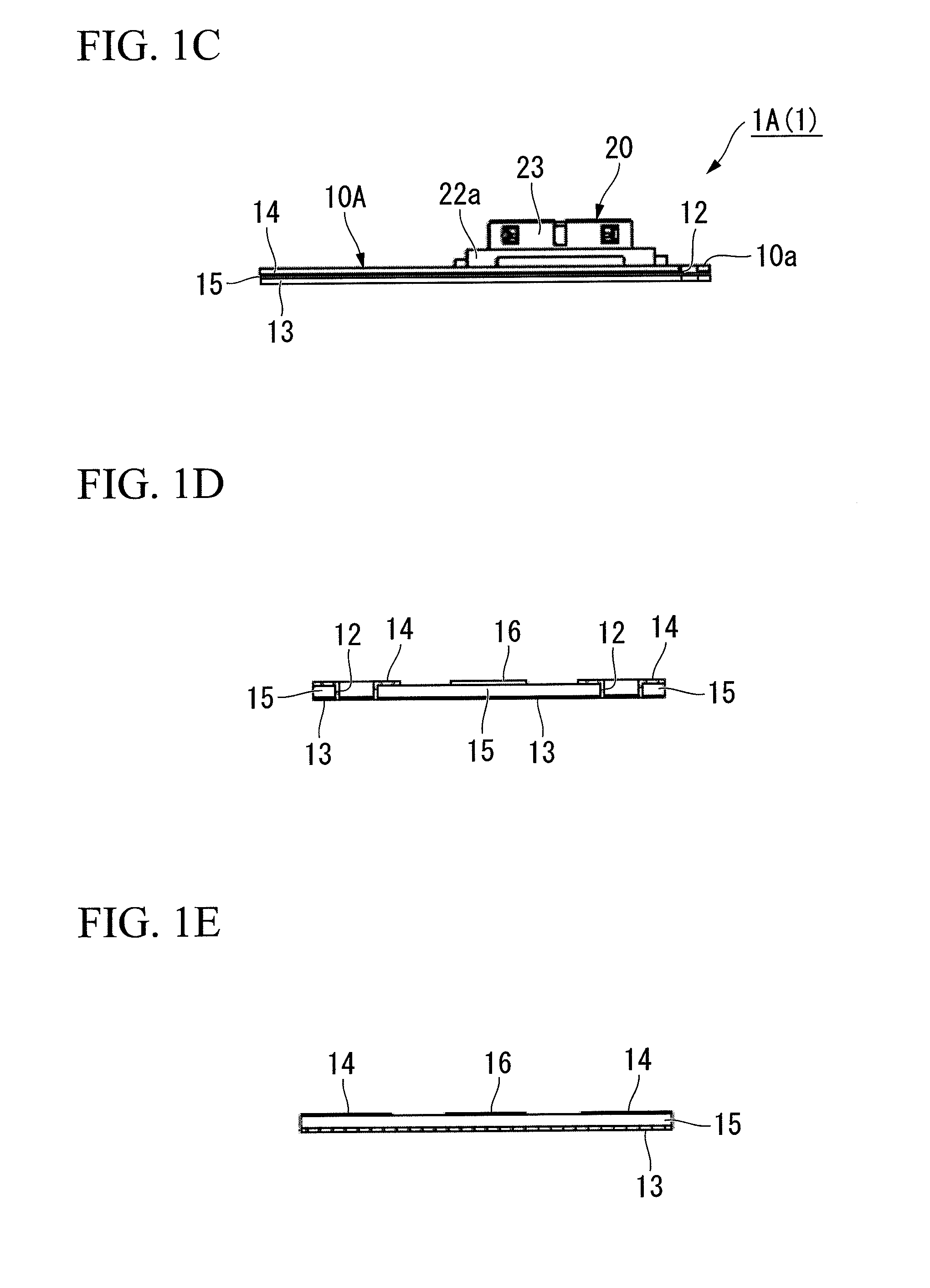
[0091]In FIGS. 5A to 5D, like constituent parts to those of the aforementioned first embodiment are designated with same reference numerals and are not repetitiously explained.
[0092]A cable connector 1C (1) of the present embodiment is different from the aforementioned cable connector 1A (1) of the first embodiment in that a wiring board 10B (10) comprises a first conductor 13, a second conductor 14, and a third conductor 17 laminated in this order respectively via an insulating material 15. The first conductor 13, the second conductor 14, and the third conductor 17 are electrically connected via through-holes...
fourth embodiment
[0105]FIG. 8 is a perspective view showing a fourth embodiment of the cable connector according to the present invention.
[0106]A cable connector 1D (1) of the present embodiment is different from the aforementioned cable connector 1C (1) of the third embodiment in that a coaxial cable 41, which is electrically connected with a signal transmission line 16, is disposed on one surface of the third conductor 17 at one end portion of the wiring board 10B.
[0107]As the coaxial cable 41, one similar to that used in the second embodiment can be used. Also in the present embodiment, a central conductor 42 of the coaxial cable 41 is electrically connected with the signal transmission line 16 via a conducting member 46, and an external conductor 44 of the coaxial cable 41 is electrically connected with the third conductor 17. In the present embodiment, there is placed a conducting member 46 in a through-hole that penetrates the third conductor 17 and the insulating material 15 placed between th...
first embodiment
[0112]FIG. 9 is a schematic perspective view showing a first embodiment of an antenna component according to the present invention and how it is used.
[0113]An antenna component 50A (50) of the present embodiment comprises: the aforementioned cable connector 1A (the wiring board 10A and the plug connector 20) of the first embodiment; and a second wiring board 60A (60). Hereinafter, the wiring board 10A of the cable connector 1A is sometimes referred to as the first wiring board 10A.
[0114]The second wiring board 60 is coupled to the first wiring board 10A. On the second wiring board 60A, there is provided an antenna 65A (65) that is electrically connected with the signal transmission line 16 of the first wiring board 10A.
[0115]As for a plurality of through-holes 12 provided along the edge portion of the first wiring board 10A, a distance d therebetween is set to a length corresponding to ½ or less of the wavelength of the frequency of the antenna 65A.
[0116]The second wiring board 60A ...
PUM
 Abstract
Description
Claims
Application Information
 - R&D
- Intellectual Property
- Life Sciences
- Materials
- Tech Scout
- Unparalleled Data Quality
- Higher Quality Content
- 60% Fewer Hallucinations
Browse by: Latest US Patents, China's latest patents, Technical Efficacy Thesaurus, Application Domain, Technology Topic, Popular Technical Reports.
© 2025 PatSnap. All rights reserved.Legal|Privacy policy|Modern Slavery Act Transparency Statement|Sitemap|About US| Contact US: help@patsnap.com


