
Heat radiation fan and method of manufacture

A heat dissipation fan and manufacturing method technology, applied in the direction of electromechanical devices, electrical components, magnetic circuits, etc., can solve the problems of many assembly steps, lack of tight connection between bearing and center column, shaking or vibration, etc., and achieve simplified assembly steps , Improve structural reliability and reduce assembly cost

Inactive Publication Date: 2008-09-10
FU ZHUN PRECISION IND SHENZHEN +1
View PDF0 Cites 9 Cited by
  • Summary
  • Abstract
  • Description
  • Claims
  • Application Information

AI Technical Summary

Problems solved by technology

[0004] During the manufacturing process of the above-mentioned cooling fan, the bearing needs to be pressed into the center column of the fan frame with a relatively large force, and the outer wall of the bearing and the inner wall of the center column generate a relatively large frictional force. Since the fan frame is made of plastic materials, it is easier to Deformation, during the assembly of the bearing to the fan frame, there will be problems such as combination tolerance and concentricity between the bearing and the center column, so that the bearing and the center column cannot achieve the purpose of tight combination, and the bearing and the center column cannot be ensured. The good concentricity between the columns will lead to shaking or vibration during the actual operation of the fan due to poor concentricity, resulting in the fan not running smoothly, resulting in noise and even premature damage to the bearing, making the quality of the fan and It is difficult to guarantee the service life; on the other hand, in the fan assembly process, there are many assembly steps required, and the assembly efficiency is not ideal, so it is necessary to overcome the above problems

Method used


Image

  • Heat radiation fan and method of manufacture
  • Heat radiation fan and method of manufacture
  • Heat radiation fan and method of manufacture

Examples


Embodiment Construction

[0020] Further description will be made below in conjunction with the embodiments with reference to the accompanying drawings.

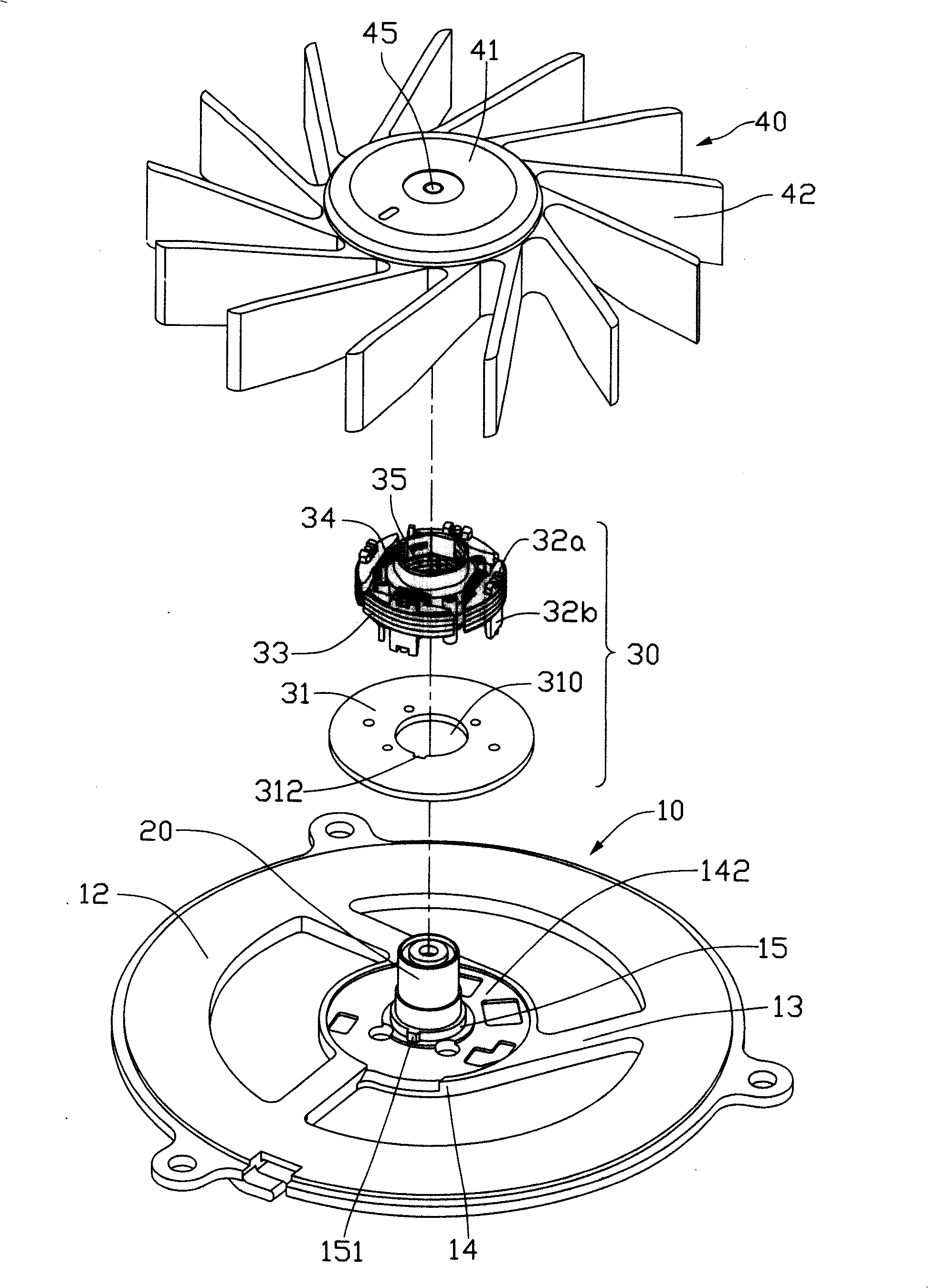
[0021] like figure 1 As shown, the cooling fan of this embodiment includes a fan frame 10 , a bearing system 20 disposed in the center of the fan frame 10 , a set of stator 30 disposed outside the bearing system 20 and a rotor 40 surrounding the periphery of the stator 30 .

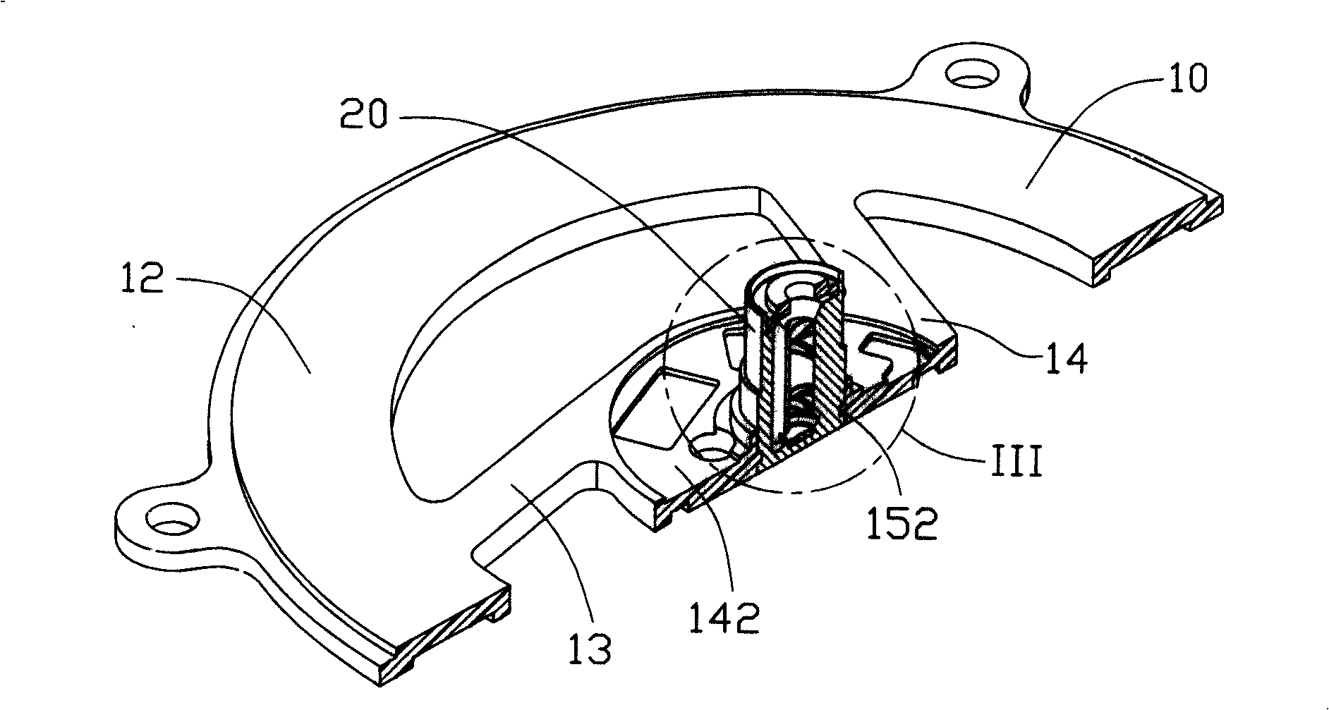
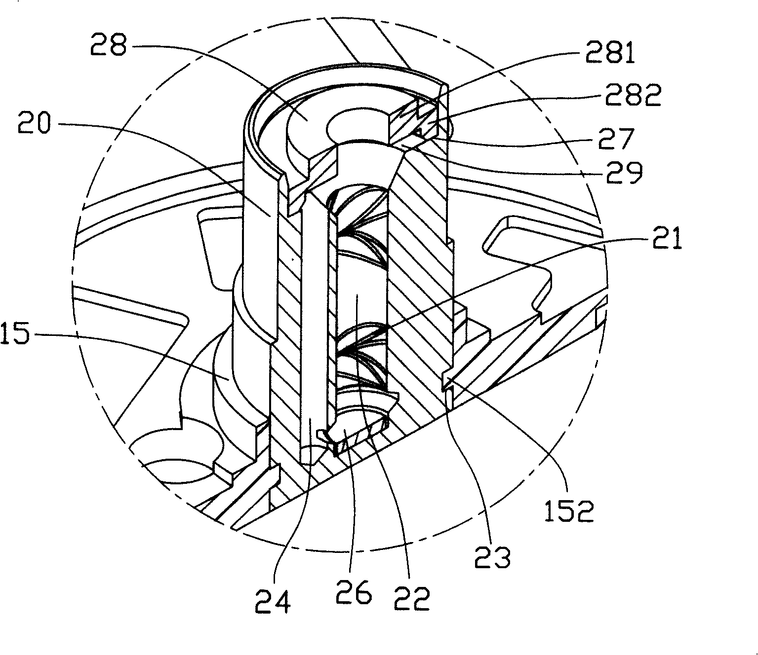
[0022] In this embodiment, the fan frame 10 includes a circular outer frame 12 , a support portion 14 located at the center of the outer frame 12 , and several ribs 13 connected between the outer frame 12 and the support portion 14 . The support portion 14 is disc-shaped, and a middle portion thereof is slightly recessed downward to form a disc-shaped receiving portion 142 . The center of the receiving portion 142 extends upwards to form a central column 15 , the central column 15 is cylindrical in shape, and the bottom end of the bearing system 20 is embedded and fixed in the ...


PUM


Abstract

The invention relates to a radiator fan, which comprises a fan frame the center of which is provided with a central cylinder, a stator which is sleeved outside the central cylinder, a bearing system which is fixed inside the central cylinder and a rotor which is supported by the bearing system. The bearing system is entirely and fixedly connected to the central cylinder of the fan frame during the process of forming the fan frame, thereby the problems of combined tolerance, concentricity and so on between the bearing system and the fan frame can be effectively prevented; the shake phenomenon is prevented during the operating process of the fan; the assembly steps are simplified and the fan performance is improved. The invention also provides a manufacturing method for the radiator fan.

Description

technical field [0001] The invention relates to a heat dissipation fan, in particular to a heat dissipation fan used for heat dissipation of electronic components and a manufacturing method thereof. Background technique [0002] With the continuous development of the electronic information industry, the operating frequency of electronic components (especially the central processing unit) continues to increase, and the heat generated by electronic components also increases, and the temperature continues to rise, which seriously threatens the performance of electronic components. To ensure the normal operation of the electronic components, a radiator is usually installed on the surface of the electronic components, and a cooling fan is installed on the radiator to assist the electronic components in cooling. [0003] The existing heat dissipation fan includes a fan frame with a central column in the center, a stator fixed outside the central column, a bearing embedded in the c...

Claims


Application Information

Patent Timeline
Patent Type & Authority Applications(China)
IPC IPC(8): F04D29/057F04D25/08
CPCF04D25/0626F04D25/0613H02K5/1675H02K5/1677H02K1/187F04D25/062F04D29/646
Inventor 张强施文章黄锐军
Owner FU ZHUN PRECISION IND SHENZHEN
Learn More