Ink ribbon cartridge

a technology of ribbon and cartridge, applied in the field ofink ribbon cartridge, can solve the problems of increasing the number of components/parts, operating noise, vibration noise, etc., and achieve the effect of eliminating operational noise and simplifying the assembly step

Inactive Publication Date: 2010-04-20
SONY CORP
View PDF27 Cites 8 Cited by
  • Summary
  • Abstract
  • Description
  • Claims
  • Application Information

AI Technical Summary

Benefits of technology

[0009]The present invention is made in view of situations and problems such as described above, and it is desirous to provide an ink ribbon cartridge that, while reducing the number of components / parts, is capable of preventing reverse rotation of a spool and is further capable of preventing occurrence of operational noise.
[0011]According to the embodiment of the present invention, the resilient engagement pieces for engagement with the ratchet gear of the spools are thus formed integrally with the cartridge body. Consequently, the number of components / parts of the non-reversing mechanism for preventing reverse rotation of the spools can be reduced, and hence the assembly step can be simplified.
[0012]Further, the respective resilient engagement pieces are in non-engagement with the ratchet gear of the spools even in use, operational noise can be eliminated.

Problems solved by technology

However, in the ink ribbon cartridge described in Patent Publication 1, during forward rotation of the spool for printing, there occurs operational noise, i.e., vibration noise, of the pawls riding over gear teeth of the ratchet gear.
With the adhesive used, while the operational noise can be restrained from occurring, the number of components / parts is increased thereby, such that an assembly step become complex.
However, similar to the above, also in the ink ribbon cartridge described in Patent Publication 2, during forward rotation of a spool for printing, there occurs operational noise, i.e., vibration noise, of the pawls riding over gear teeth of the ratchet gear.
Further, in the ink ribbon cartridge disclosed in patent publication 2, the pawls are separate members from the body of the cartridge, the number of components / parts is increased thereby, such that an assembly step become complex.
In the ink ribbon cartridge also, since the leaf spring is used, the number of components / parts cannot be reduced.

Method used


Image

  • Ink ribbon cartridge
  • Ink ribbon cartridge
  • Ink ribbon cartridge

Examples


Embodiment Construction

[0019]An ink ribbon cartridge 1 employing an embodiment of the present invention will be described herebelow with reference to the accompanying drawings.

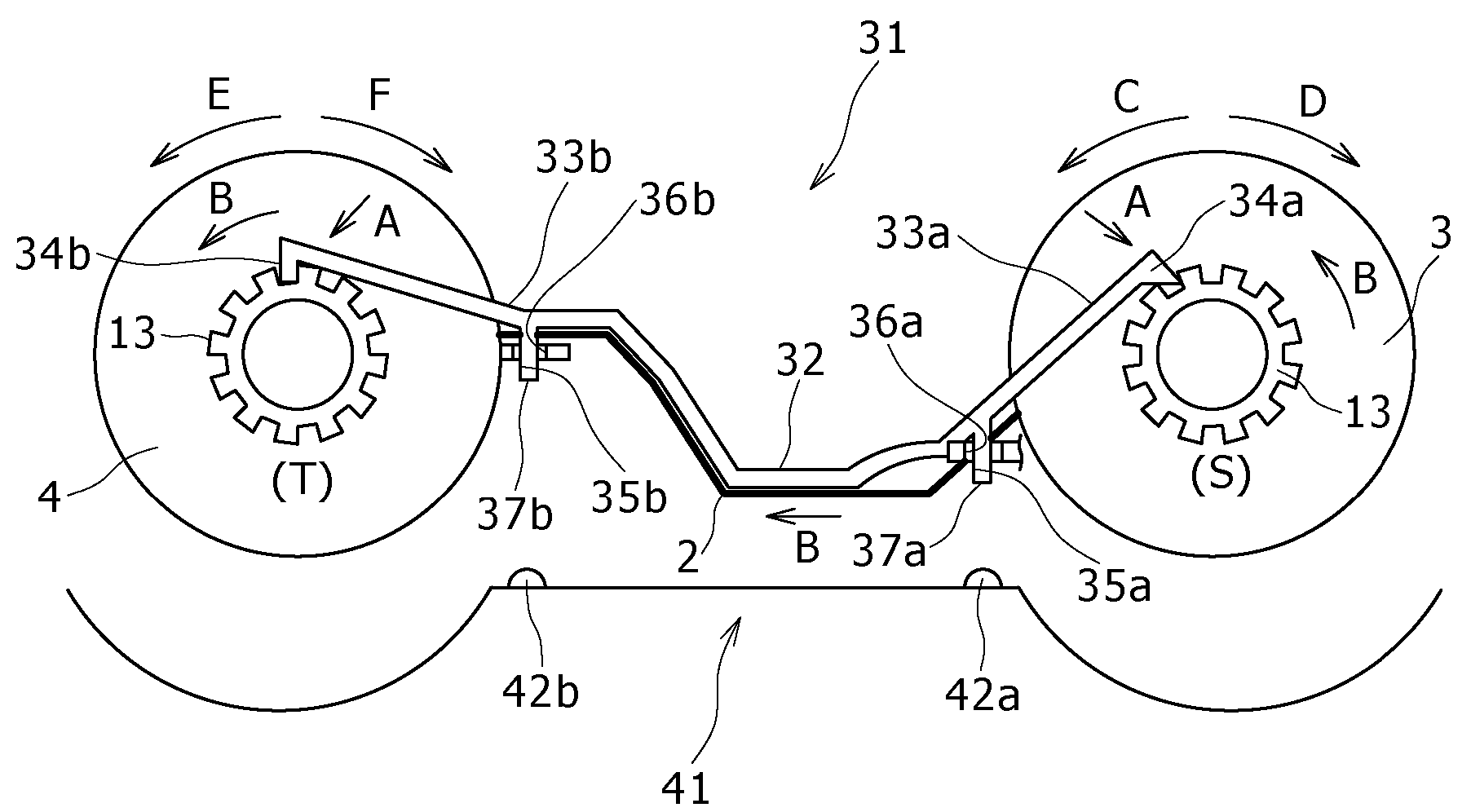
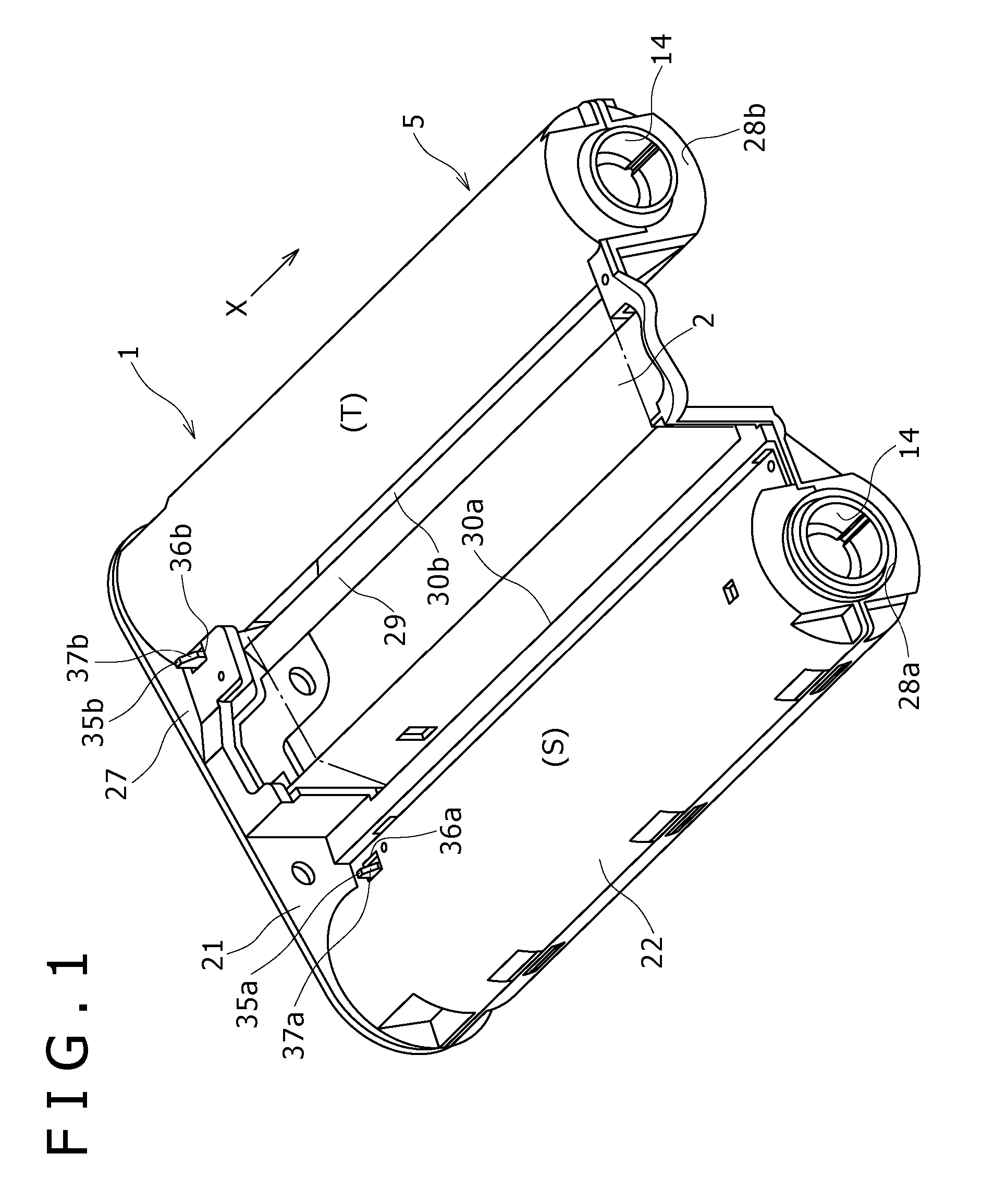
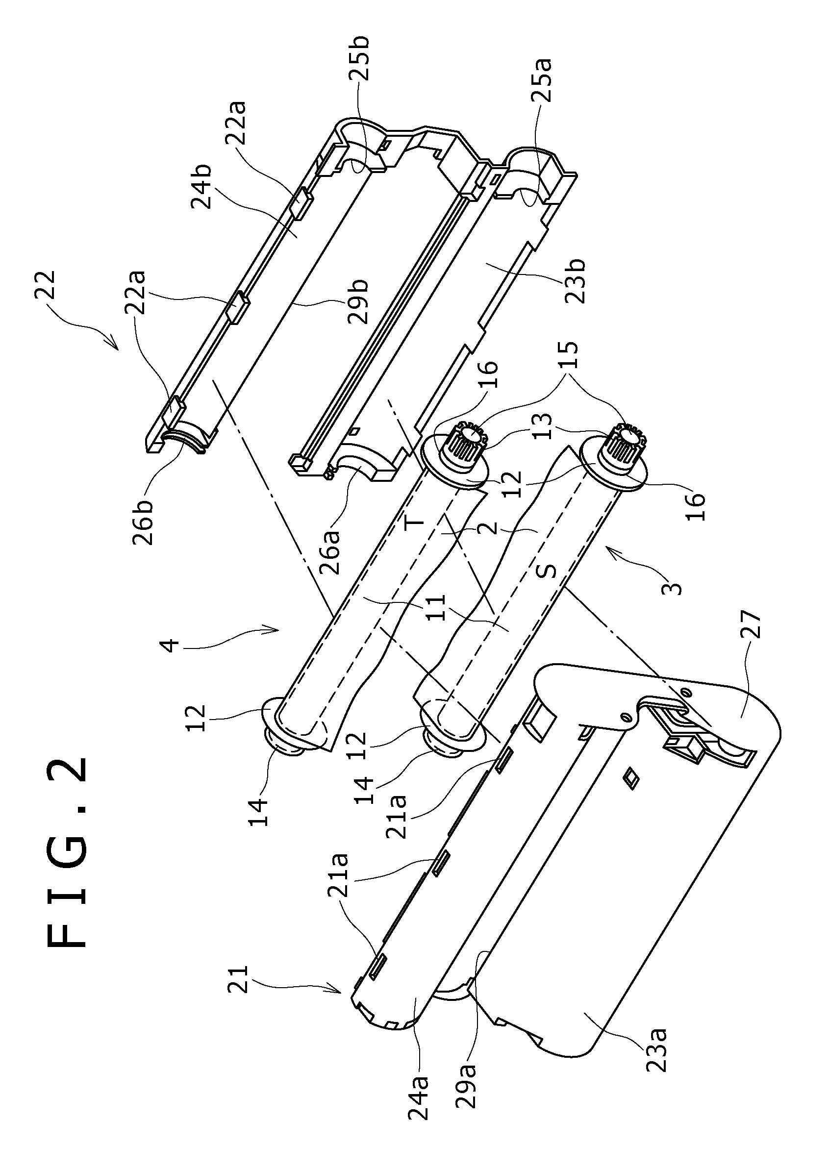
[0020]Referring to FIG. 1, the ink ribbon cartridge 1 employing an embodiment of the present invention is attached to a thermal transfer printer apparatus that thermally transfer dyes onto a printing paper to thereby perform color printing onto the printing paper. With reference to FIGS. 1 and 2, the ink ribbon cartridge 1 includes a supply spool3, a take-up spool 4, and a cartridge body 5. The supply spool 3 holds an ink ribbon 2 wound thereabout, in which the ink ribbon 2 includes dye layers to be transferred onto the printing paper. The take-up spool 4 takes-up the ink ribbon 2. The cartridge body 5 houses the supply and take-up spools 3 and 4 that, respectively, hold ink ribbon 2 wound thereabout.

[0021]More specifically, the ink ribbon 2 has yellow (Y), magenta (M), and cyan (C) ink layers respectively formed of sublimable and t...


PUM


Abstract

An ink ribbon cartridge includes spools each including a ratchet gear in one end portion. A cartridge body includes integrally formed resilient engagement pieces each including a ratchet portion that engages and disengages the ratchet gear of the respective spool and a compressed portion that is compressed by a compressing portion of a thermal transfer printer apparatus. When the ink ribbon cartridge is installed in the thermal transfer printer apparatus, the resilient engagement pieces behave such that the compressed portions are compressed by the compressing portions of the thermal transfer printer apparatus. Thereby, engagement between the ratchet gears of the respective spools and the ratchet portions is released, and the spools become rotatable in the cartridge body.

Description

CROSS REFERENCES TO RELATED APPLICATIONS[0001]The present invention contains subject matter related to Japanese Patent Application JP 2005-288795 filed in the Japanese Patent Office on Sep. 30, 2005, the entire contents of which being incorporated herein by reference.BACKGROUND OF THE INVENTION[0002]1. Field of the Invention[0003]The present invention relates to an ink ribbon cartridge that prevents reverse rotation of spools that hold an ink ribbon wound thereabout.[0004]2. Description of the Related Art[0005]Thermal transfer printer apparatuses use an ink ribbon cartridge. An ink ribbon cartridge containing an ink ribbon is installed in a thermal transfer printer apparatus, in which the ink ribbon and printing paper are driven to travel between a thermal head and a platen roller provided in a position opposite to the thermal head. In addition, thermal energy is applied by the thermal head to the ink ribbon, and dies of the ink ribbon are thermally transferred, whereby an image is ...

Claims


Application Information

Patent Timeline
Patent Type & Authority Patents(United States)
IPC IPC(8): B41J35/28
CPCB41J33/52B41J17/32B41J32/00B41J33/16B41J33/18B41J2/315
Inventor DOCHI, KIYOTAKAKAMODA, HITOSHI
Owner SONY CORP
Why Eureka
Try Eureka