Drive system of a utility vehicle

a technology of drive system and utility vehicle, which is applied in the direction of propulsion parts, mechanical equipment, transportation and packaging, etc., can solve the problem of not allowing any useful conclusion, and achieve the effect of less space and greater safety

Inactive Publication Date: 2006-05-16
DEERE & CO
View PDF18 Cites 35 Cited by
  • Summary
  • Abstract
  • Description
  • Claims
  • Application Information

AI Technical Summary

Benefits of technology

[0009]An object of the invention is to provide such a drive system which includes a control arrangement together with requisite drive speed and pressure sensor for controlling the pump and motor units of the hydrostatic transmission in such a way as to prevent the motor unit(s) from being driven like a pump.
[0011]In this way, the control arrangement receives two items of information that are independent of each other about the operating condition of the hydraulic motor. The pressure difference between the inlet and the outlet of the hydraulic motor, measured by the pressure sensor, contains information about the force mechanically transmitted from the hydraulic motor to the ground (or the torque or the power). On the basis of the signal of the pressure sensor, it is then possible to recognize whether the wheel is driving the utility vehicle when the pressure at the inlet is greater than at the outlet, or whether the wheel is spinning when the pressure at the inlet is approximately equal to the pressure at the outlet, or whether the wheel is rotated in a direction opposite to the intended direction of rotation by a further hydraulic motor acting as a pump, for example, on an incline, that is, it is subject to the back-spin effect, when the pressure at the outlet is greater than at the inlet. In addition, the rotational speed of the wheel is detected by the rotational speed sensor. On the basis of the signals from both sensors the control arrangement is in the position to induce the actuator to adjust the fluid displacement of the hydraulic motor in such a way that the wheel rotates in the desired direction with the desired rotational speed. By the use of the feedback of both items of information about the operating condition of the wheel an adaptive control system results. In traction operation, for example, during braking or operating down-slope, a blocking or reverse rotation of driven rear wheels can be avoided. In this case the rear wheels are not stopped which would lose their braking effect, but are supplied with a hydraulic fluid flow adapted to the particular situation. During operation uphill in reverse, the hydraulic flow is not lost to spinning rear wheels, but is conducted to the front wheels.
[0012]In case of necessity, the invention makes possible a gentle change in the position of the actuator, so that jerky decelerations or accelerations of the utility vehicles are avoided. In operating uphill, forward as well as backward, the regulation of the fluid displacement of the hydraulic motor results in optimum traction even at a rear axle which is loaded less heavily than the front axle. During operation downhill, the drive system prevents the rear wheels from rotating backwards or remaining stopped. The utility vehicle can be steered with a much greater degree of safety. In comparison to mechanical all-wheel drives, the drive system is very advantageous, since it requires less space, wheels of any desired size can be used, and the power of the drive is automatically applied at the location where it can also be transmitted to the ground. Since no universally jointed shaft is required, the invention can also be applied to combines.
[0016]Many utility vehicles are provided with two driven axles. An obvious solution is to also associate at least one (second) hydraulic motor with the second axle, that is supplied with pressurized hydraulic fluid from the hydraulic pump. The axle that is less critical from the traction standpoint and that is the front axle in the case of harvesting machines that carry the greatest axle load, as a rule, can be associated with a second hydraulic motor with fixed fluid displacement, since spinning of the wheels or track drives of this axle that is loaded with a greater load than the other axle is relatively unlikely. Thereby the cost of a second hydraulic motor with variable fluid displacement can be eliminated.
[0019]With utility vehicles, two driven axles wheels of differing diameters are frequently applied to the two axles. Often the wheels are exchanged with wheels of different diameters, that just happen to be available. In order to assure that the wheels of both axles are driven at the same circumferential speed—in order to avoid unnecessary wear of the treads of the wheels—it is appropriate after each change of the size of the wheels to make the gear ratio of the drives of the wheels conform with the actual size of the wheels. This conformity could be performed in mechanical drives by a costly change in the gear ratio. In a hydraulic drive, according to the invention in which the wheels of two axles are each driven by a hydraulic motor, of which at least one is provided with a variable fluid displacement, it is possible by means of the control arrangement and the actuator to obtain an automatic conformity of the gear ratio. In a simple embodiment, information is manually provided as input about the ratio of the wheel sizes of the first and second axle. During the operation, this information is considered by the control arrangement in the control of the actuator. In a comfortable embodiment, a calibration mode can be selected by means of a corresponding input in an input arrangement. In the calibration mode that is preferably performed most appropriately on a surface that is not critical in regard to traction, the control arrangement detects the rotational speeds of the wheels of both axles, from which the aforementioned information about the ratio of the wheel sizes is derived. Then the control arrangement controls the actuator in such a way that the circumferential speed of the wheels of both axles is equal. This thought deserves independent inventive status.

Problems solved by technology

In such hydraulic all-wheel drives there is a problem in certain operating situations, particularly in operating downhill, when a greater load is applied to the front axle than to the rear axle.
Operating situations are conceivable in which a single sensor detects either the rotational speed of a wheel or the pressure difference in the supply line of a hydraulic motor, and delivers a measured value, that does not permit any useful conclusion as to the operating situation and the measures that are to be taken.

Method used


Image

  • Drive system of a utility vehicle
  • Drive system of a utility vehicle
  • Drive system of a utility vehicle

Examples


second embodiment

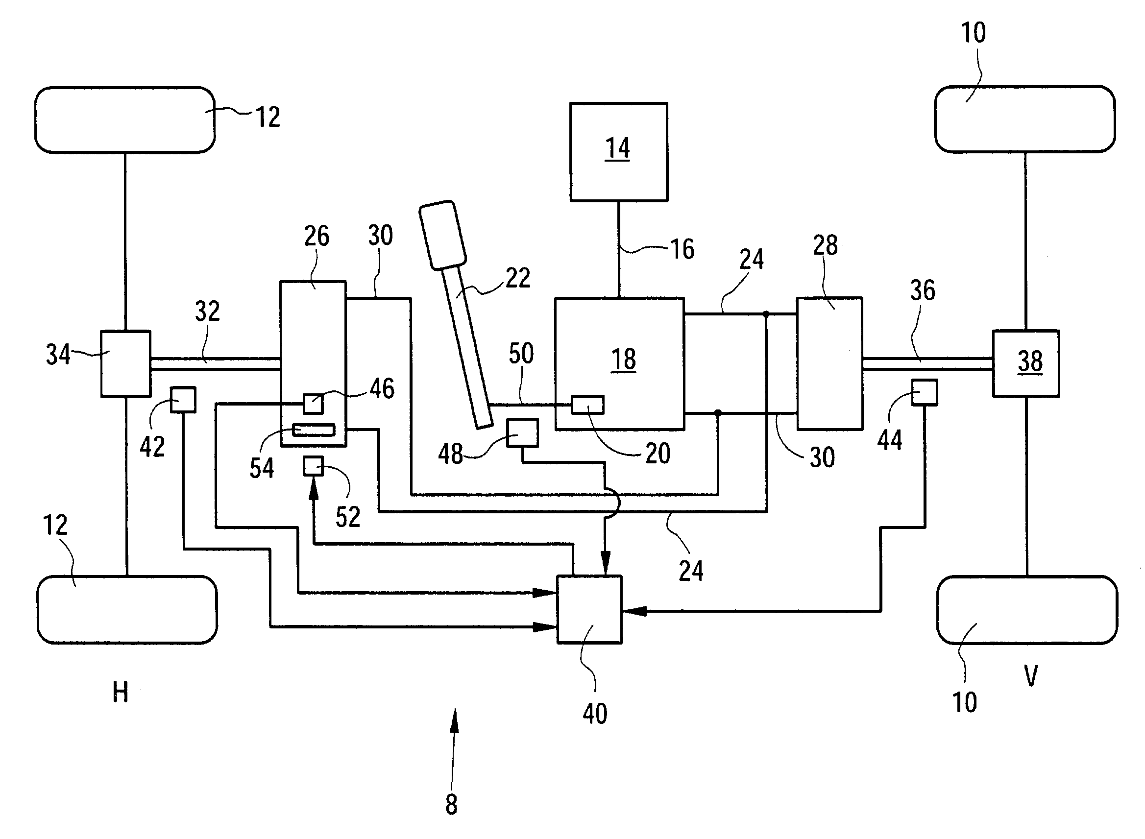
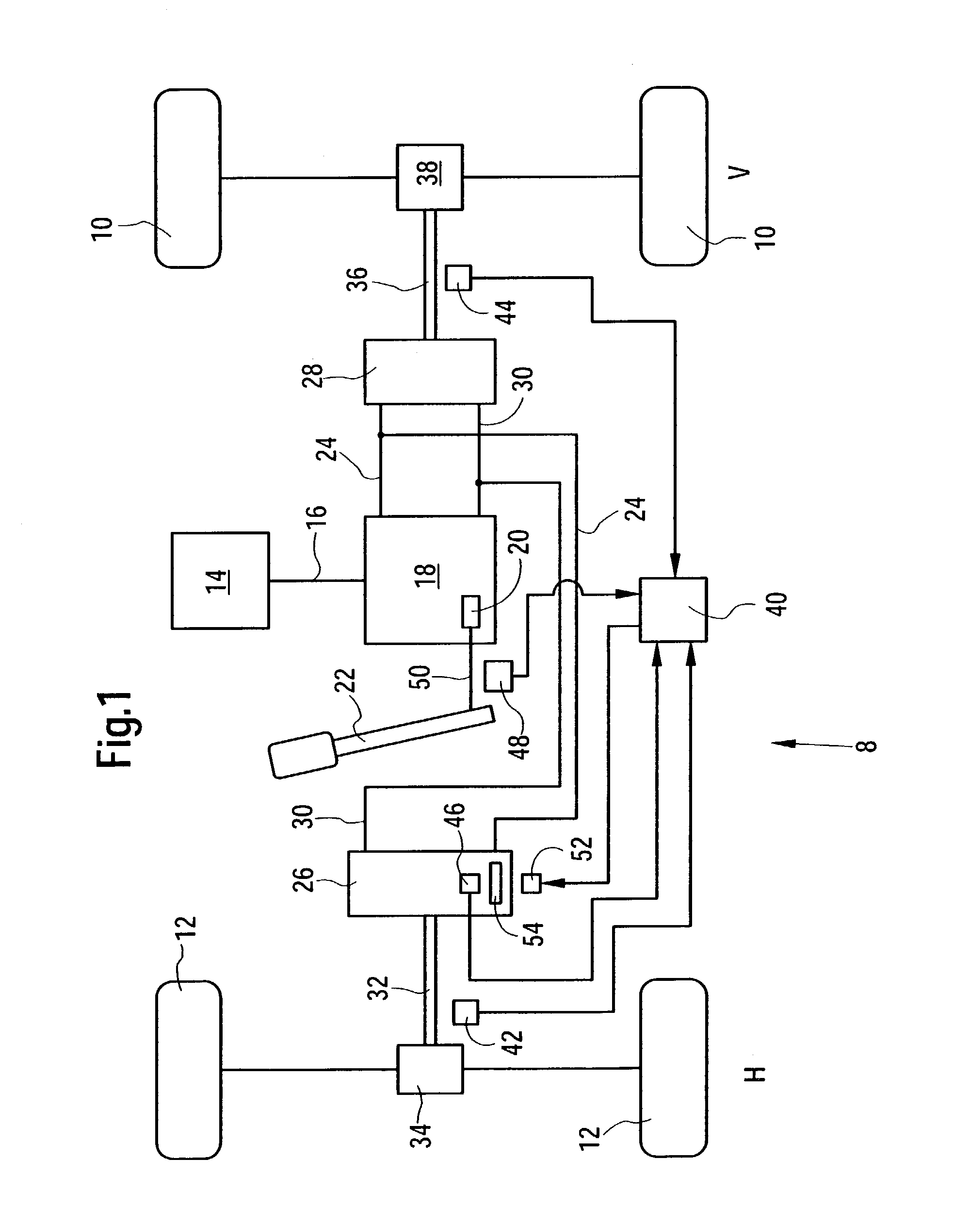
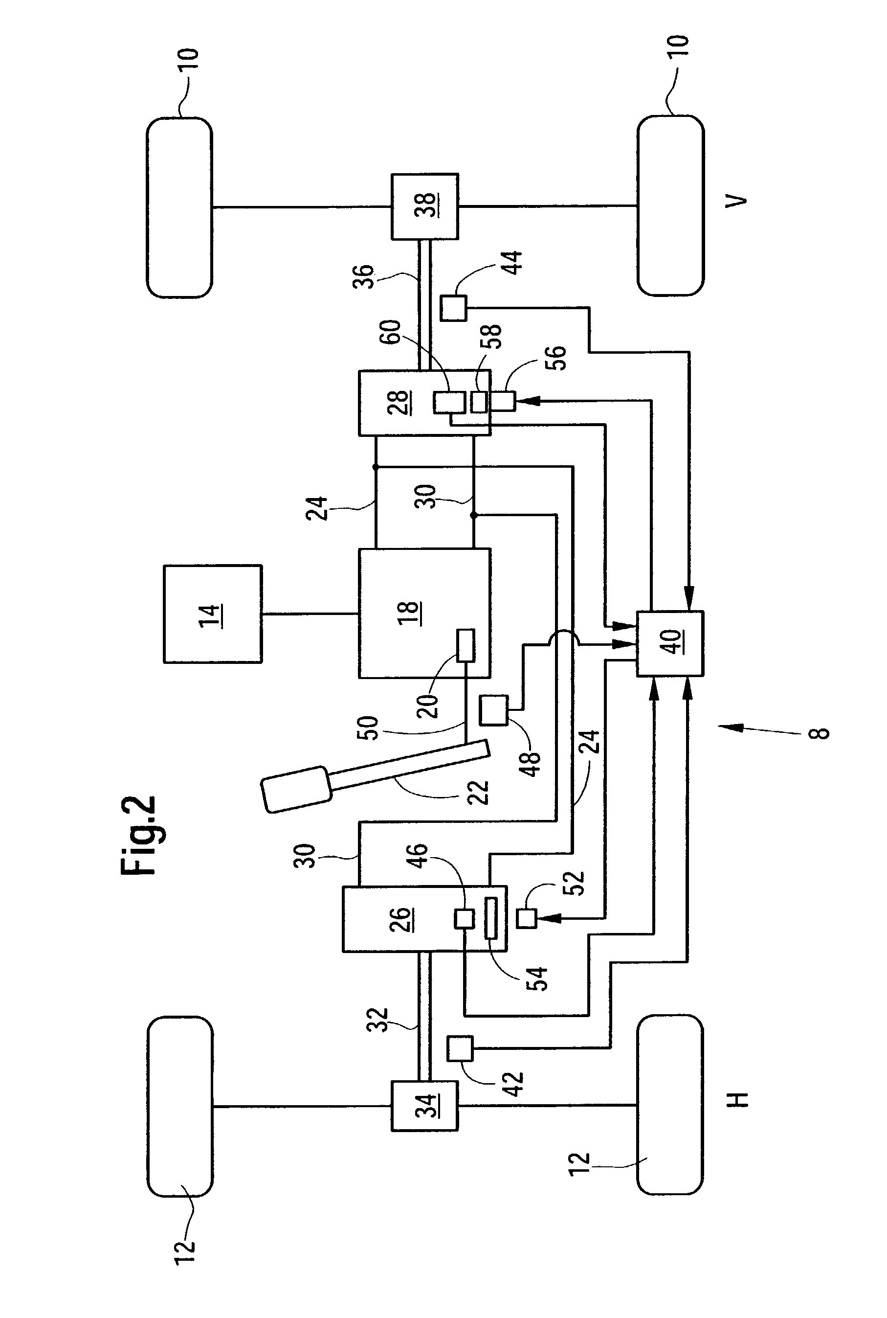
[0035]The rotational speed sensors 42 and 44 measure the actual velocity of the utility vehicle 8. When this reaches or exceeds a predetermined maximum speed specific to a given country, the control arrangement 40 induces the third actuator 62 to bring the swash plate 20 of the hydraulic pump 18 into a position that corresponds to a lower velocity. This provides assurance that the allowable maximum speed is maintained. Furthermore the control arrangement 40 detects the operating conditions of the first and the second hydraulic motors 26 and 28, as in the case of the second embodiment and controls the two actuators 52 and 56 in such a way that an optimum operating condition of the hydraulic motors 26 and 28 is achieved.

third embodiment

[0036]In the third embodiment, the main engine 14 is associated with a load sensor 64 in the form of a rotational speed sensor that detects the rotational speed of the main engine 14. On the upper side of the operating control lever 22, an input arrangement 66 is arranged that includes several manually operated keys. The input arrangement 66 and the load sensor 64 are connected with the control arrangement 40.

[0037]The input arrangement 66 permits the selection of an operating mode in which the forward propulsion velocity is set automatically. The control arrangement 40 induces the third actuator 62 to bring the swash plate 20 into a position that corresponds to a velocity that is preset by the operating control lever 22. In case the signal of the load sensor 64 ever indicates that the rotational speed of the main engine 14 has fallen off due to an excessive load, for example, if a chopper arrangement or a threshing and separating arrangement is loaded to a greater degree than that ...


PUM


Abstract

A drive system for use in utility vehicles, such as agricultural forage harvesters and combines, includes a hydrostatic transmission having a pump driven by a main engine of the vehicle and having first and second motors respectively coupled to front and rear axles of the vehicle by way of first and second differential gear sets. The pump and one or both of the motors have a variable displacement determined by positioning respective swash plates through the agency of a lever, in the case of the pump, and by electronic devices, in the case of the motors, the electronic devices acting in response to control signals sent by a control arrangement, which in turn, operates in response to signals produced by pressure sensors associated with the motors and by signals produced by speed sensors associated with output shafts of the hydraulic motors. The control arrangement has a memory for storage of data, such as maximum legal ground speed and the ratio of the speeds of the axles as results from a given wheel size, and uses this information for controlling the hydrostatic transmission such that the vehicle does not exceed the speed, and the front and rear axles are driven so as to produce the same ground speed.

Description

FIELD OF THE INVENTION[0001]The invention concerns a drive system of a utility vehicle, with a main drive engine, that is connected so as to drive a hydraulic pump, that is connected with a hydraulic motor so as to conduct hydraulic fluid which is connected so as to drive at least one wheel that is in engagement with the ground and whose fluid displacement can be varied by an actuator connected to a control arrangement, where the control arrangement is connected with a rotational speed sensor arranged to detect the rotational speed of the wheel and that can be operated to control the actuator as a function of the signals of the rotational speed sensor.BACKGROUND OF THE INVENTION[0002]In many utility vehicles, such as agricultural vehicles and harvesting machines, hydraulic drives are applied. They include a pump driven by an internal combustion engine and a motor connected to the pump so as to conduct hydraulic fluid, that drives a wheel or several wheels. In some vehicles the wheel...

Claims


Application Information

Patent Timeline
Patent Type & Authority Patents(United States)
IPC IPC(8): B60K17/00F16H59/44F16H61/42F16H61/427F16H61/46F16H61/47F16H61/472
CPCF16H61/42F16H61/47F16H61/472F16H61/427B60W2300/158F16H59/44F16H2059/683
Inventor KEMPF, BERNDHOFER, JURGENBOHRER, STEFAN
Owner DEERE & CO
Why Eureka
Try Eureka