Electrohydraulic energy regenerative vibration absorber

A technology of shock absorber and accumulator, applied in the direction of liquid shock absorber, etc., can solve the problems of low efficiency of energy feed system, inferior to passive suspension, low overall system efficiency, etc., and achieve the effect of active control

Inactive Publication Date: 2010-12-29
WUHAN UNIV OF TECH
View PDF10 Cites 34 Cited by
  • Summary
  • Abstract
  • Description
  • Claims
  • Application Information

AI Technical Summary

Problems solved by technology

The disadvantage of the energy recovery system that uses mechanical devices such as rack and pinion or ball screw to convert linear motion into rotation is: affected by the internal clearance of the transmission system, the frequency response function of the system to high-frequency signals is not zero
For example, when the ball screw type is in the low frequency range and the ground excitation amplitude is large, its energy recovery efficiency and suspension characteristics are better; but when the system frequency is high, its suspension characteristics are not as good as passive suspensions, and energy cannot be recovered. lead to lower overall system efficiency
[0007] In the above technology of converting linear motion into rotation, the motor and the transmission system are connected in a solid state, which causes the motor to continuously change the rotation direction and repeat the motor speed from 0->acceleration->deceleration->motor speed 0 as the system vibrates cycle, creating a large "inertia loss"
This will not only greatly shorten the life of the generator, but also make the generator have little or no time to generate electricity during the entire vibration process, resulting in low efficiency of the entire energy feeding system, so that it cannot be applied to practical applications

Method used


Image

  • Electrohydraulic energy regenerative vibration absorber
  • Electrohydraulic energy regenerative vibration absorber

Examples


Embodiment Construction

[0019] The present invention will be further described below in combination with specific embodiments and accompanying drawings.

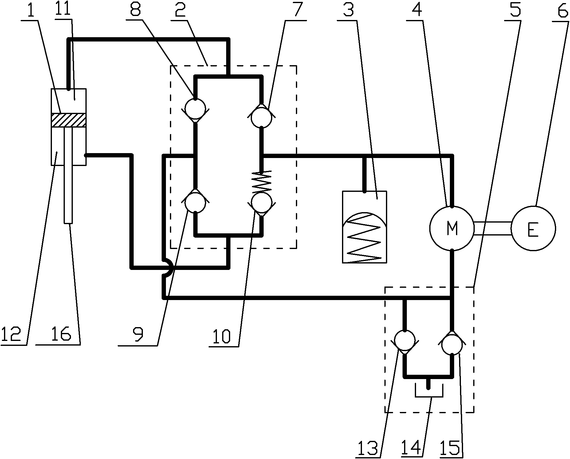
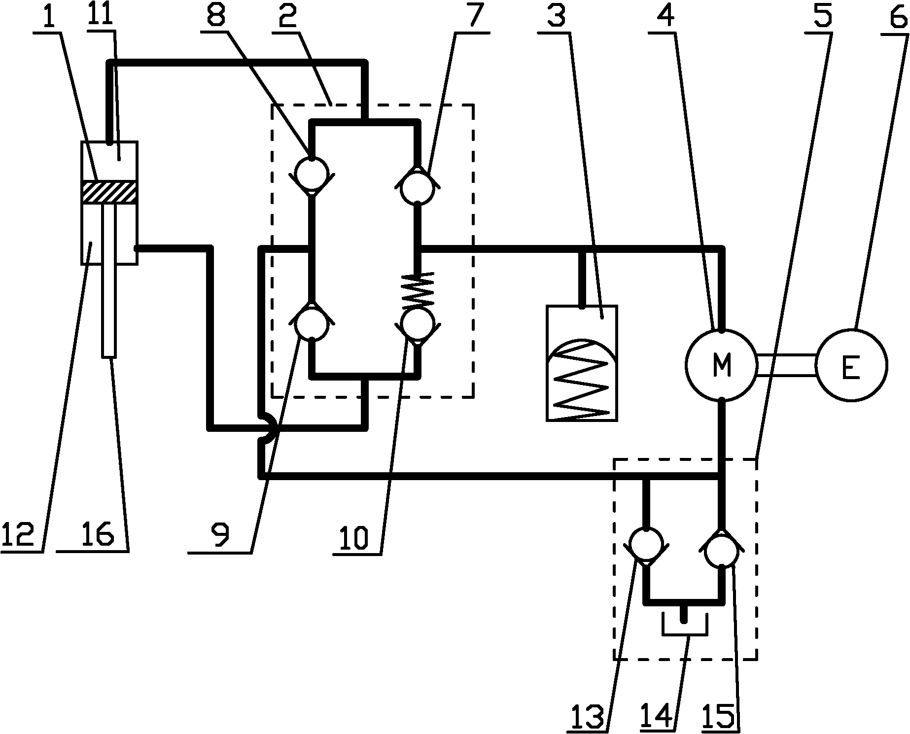
[0020] The liquid-electric energy-feeding shock absorber provided by the present invention has a structure such as figure 1 As shown, it includes piston 1, hydraulic check bridge 2, accumulator 3, hydraulic motor 4, volume conversion bridge 5 and rotary generator 6, wherein: the shock absorber cavity is divided into no The rod cavity 11 and the rod cavity 12, each of these two parts of the cavity has an oil outlet and an oil inlet, and each oil outlet and oil inlet is provided with a one-way valve, and the one-way valve is connected with it The connected pipeline constitutes the hydraulic check bridge 2; the accumulator 3 is connected in parallel on the connecting pipeline between the two oil outlets and the oil inlet of the hydraulic motor 4; between the oil outlet of the hydraulic motor 4 and the shock absorber cavity A volume conversion bridge ...


PUM


Abstract

The invention relates to an electrohydraulic energy regenerative vibration absorber, which comprises a piston, a hydraulic check bridge, an accumulator, a hydraulic motor and a rotary generator. A vibration absorber cavity is divided into a rodless cavity (11) and a rod cavity (12) by a piston and a piston push rod (16); the two cavities are provided with an oil outlet and an oil inlet respectively; each oil outlet and each oil inlet are provided with a one-way valve; the one-way valve and a pipeline which is connected with the one-way valve form the hydraulic check bridge; the accumulator is connected in parallel on a connecting pipeline between two oil outlets and an oil inlet of the hydraulic motor; a volume conversion bridge (5) is connected in parallel on a pipeline between the oil outlet of the hydraulic motor and two oil inlets of the vibration absorber cavity; and the volume conversion bridge consists of two one-way valves and an oil tank which is connected with the one-way valves. The electrohydraulic energy regenerative vibration absorber meets the damping force requirement of an automobile vibration absorber, and can convert the ground vibration into direction-invariable rotary movement to drive the generator to generate power and actively control the damping of the vibration absorber by controlling the generator load.

Description

technical field [0001] The invention relates to a shock absorber, in particular to a hydraulic-electric energy-feeding shock absorber for a vehicle suspension system, which has the function of recovering a part of the vibration energy and can also be used as an actuator to realize the active movement of the suspension system. or semi-active control. Background technique [0002] When the vehicle is running on the road, the bumps of the road and the acceleration and deceleration of the vehicle, steering and other operations will cause relative vibration between the sprung mass and the unsprung mass, and the shock absorber converts this part of mechanical energy into heat energy consumption in the form of friction Dissipate, thereby attenuating the vibration of the vehicle. If these energies can be recycled, the energy consumption of vehicles can be reduced, thereby achieving the purpose of saving energy. The present invention is just based on such an idea, that is, replacin...

Claims


Application Information

Patent Timeline
Patent Type & Authority Applications(China)
IPC IPC(8): F16F9/19
Inventor 过学迅徐琳杨波张成才刘健袁龙
Owner WUHAN UNIV OF TECH
Why Eureka
Try Eureka