
Cooling fan and assembly method thereof

一种散热风扇、组装方法的技术,应用在泵装置、机电装置、电动组件等方向,能够解决组装不便、无法确保电路板绝缘效果、轴向高度无法缩减等问题,达到降低轴向高度、提升组装便利性、佳定位功效的效果

Active Publication Date: 2013-03-27
SUNONWEALTH ELECTRIC MACHINE IND
View PDF9 Cites 9 Cited by
  • Summary
  • Abstract
  • Description
  • Claims
  • Application Information

AI Technical Summary

Problems solved by technology

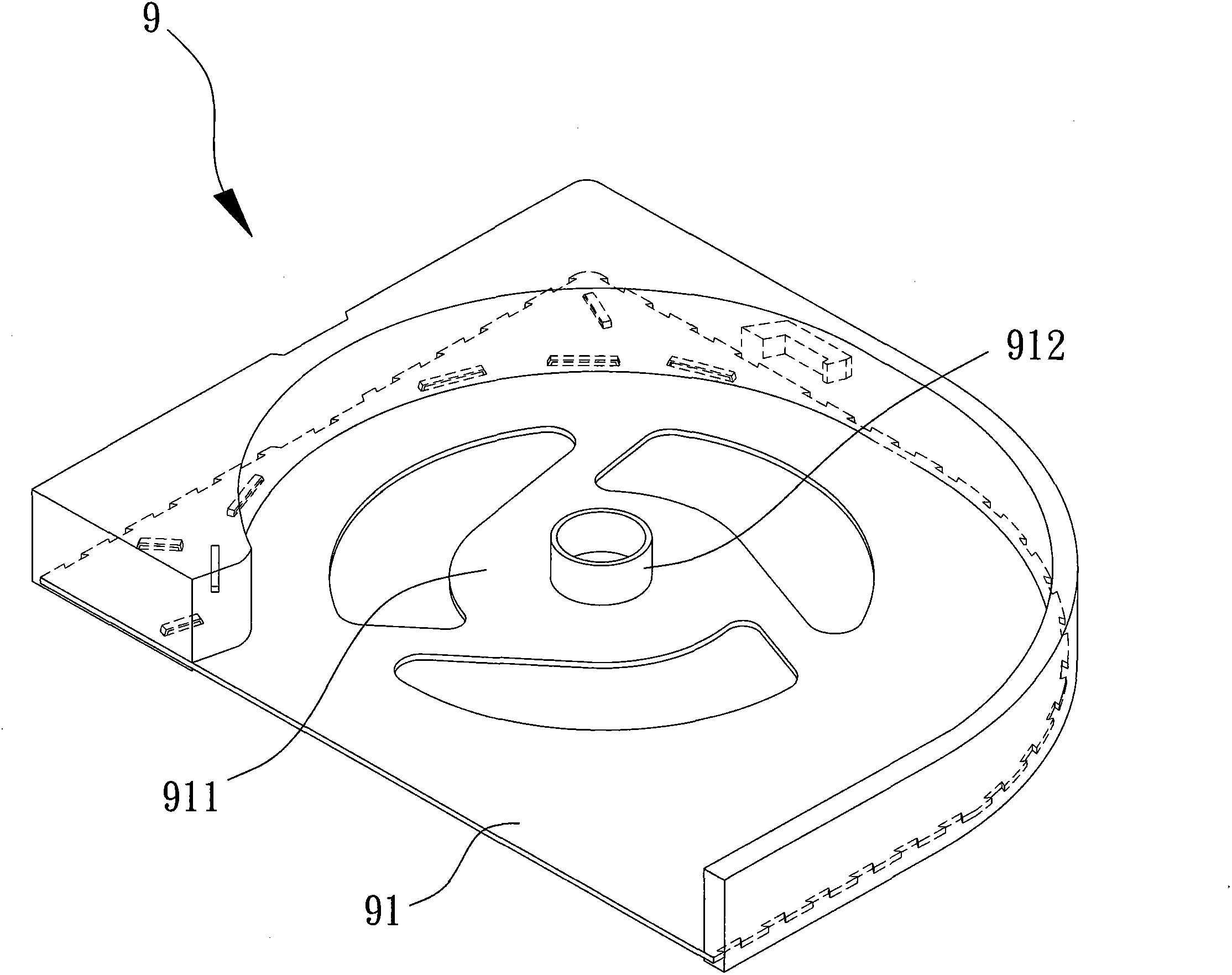
[0006] Although the existing fan frame body 9 can provide a metal base 911 with better structural strength and quality, yet, the existing fan frame body 9 is for those skilled in the art to supply parts such as stator groups (comprising coils or circuit boards). It can be understood that when assembling components such as the fan blade set and the fan blade set, the stator set must first be assembled with silicon steel sheets, coils and circuit boards, and then the stator set and the metal base 911 are assembled together. , therefore, still as before figure 1 The existing cooling fan 8 shown has many problems such as inconvenient assembly and inability to reduce the axial height. More importantly, when the stator group is combined with the metal base 911, since the metal base 911 is made of metal material, the , it is still impossible to ensure a good insulation effect between the circuit board of the stator group and the metal base 911

Method used


Image

  • Cooling fan and assembly method thereof
  • Cooling fan and assembly method thereof
  • Cooling fan and assembly method thereof

Examples


Embodiment Construction

[0074] In order to make the above-mentioned and other objects, features and advantages of the present invention more comprehensible, the preferred embodiments of the present invention are specifically cited below, together with the accompanying drawings, as follows:

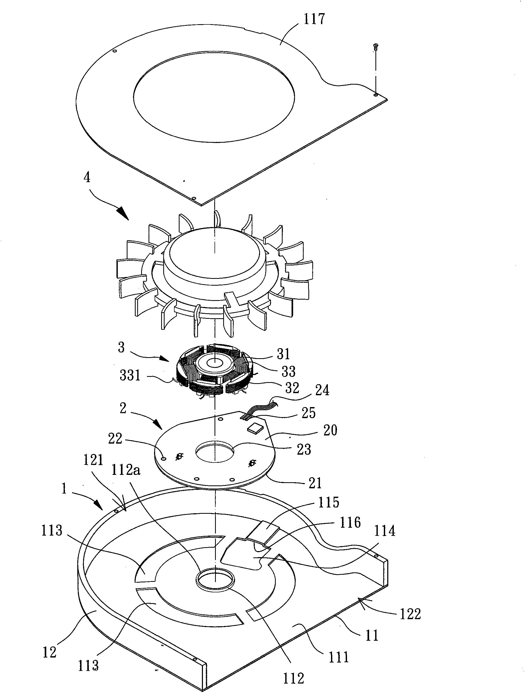
[0075] Please refer to image 3 As shown, the cooling fan of the present invention at least includes a fan frame 1 , a circuit board 2 , a stator coil assembly 3 and a fan wheel 4 . The fan frame 1 can be combined with the circuit board 2, the circuit board 2 is used for external power supply or drive circuit, the stator coil group 3 is combined inside the fan frame 1 and used to electrically connect the circuit board 2, the fan wheel 4 The stator coil set 3 can be rotatably combined to drive the fan wheel 4 to rotate by using the stator coil set 3 .

[0076] The fan frame 1 includes a metal base 11 and a side wall 12 . The metal base 11 has a joint surface 111 and a joint portion 112, the joint portion 112 is ...


PUM


Abstract

A cooling fan includes a fan frame, a circuit board, a stator-coil unit and an impeller. The fan frame includes a metal seat and a lateral wall. The metal seat comprises an engaging face and an engaging portion arranged on the engaging face. The lateral wall is arranged on a periphery of the metal seat and includes an air inlet and an air outlet. The circuit board includes a positioning hole. The circuit board is press fitted around the engaging portion of the metal seat via the positioning hole and adhered to the engaging face of the metal seat. The circuit board includes an insulation layer facing the metal seat. The stator-coil unit is mounted on the metal seat of the fan frame and electrically connected to the circuit board. The impeller is rotatably coupled with the stator-coil unit. Therefore, the Cooling fan and the assembly method thereof can simplify the assembling step and improve the assembling convenience, and can effectivley reduce the axial height of the cooling fan.

Description

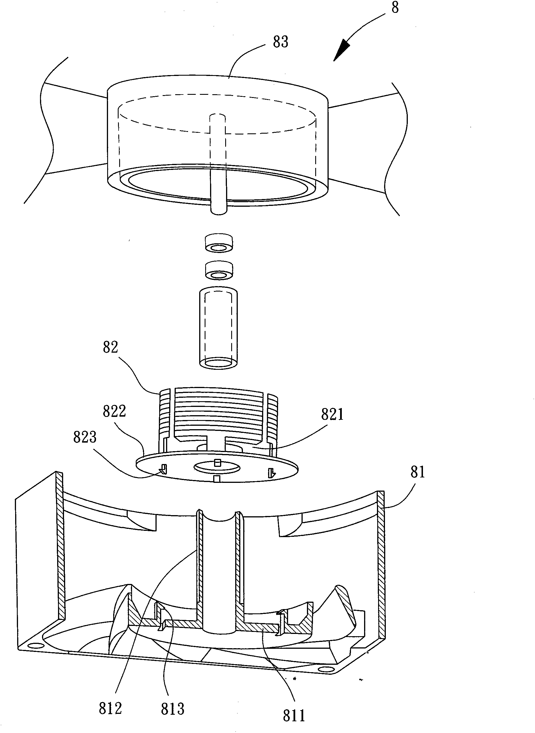
technical field [0001] The invention relates to a heat dissipation fan and its assembly method, in particular to a heat dissipation fan and its assembly method which are easy to combine the circuit board with the metal base and ensure the insulating effect between the circuit board and the metal base. Background technique [0002] Please refer to figure 1 As shown, it is a fixing structure of a cooling fan stator group disclosed in the Taiwan Patent No. M387164. The existing cooling fan 8 includes a casing 81, a stator set 82 and a fan blade set 83; the casing 81 is integrally injection-molded with a fan seat 811 and a central shaft column 812, and the fan seat 811 is provided with a first Engaging portion 813 ; the stator assembly 82 has a stator 821 composed of silicon steel sheets and coils, the stator 821 is combined with a circuit board 822 , and the stator 82 is provided with several second engaging portions 823 . [0003] When the existing cooling fan 8 is actually ...

Claims


Application Information

Patent Timeline
Patent Type & Authority Applications(China)
IPC IPC(8): F04D25/08F04D29/64
CPCF04D25/0646H02K15/14F04D25/08F04D25/0693F04D25/0633F04D17/16F04D25/0613F04D25/06F04D29/4226F04D29/601Y10T29/49009
Inventor 吴清林
Owner SUNONWEALTH ELECTRIC MACHINE IND
Learn More