
System and method for making busses limited to a linear topology extensible to other topologies

a topology and bus technology, applied in the field of bus communication, can solve the problems of not being able to record all of the transactions on the bus, and not being able to meet the requirements of the 1553 system or its equivalen

Active Publication Date: 2013-09-24
GE AVIATION SYST LLC
View PDF9 Cites 7 Cited by
  • Summary
  • Abstract
  • Description
  • Claims
  • Application Information

AI Technical Summary

Benefits of technology

The patent describes a communication system and method that includes a main bus, a bus controller and three remote terminals. The main bus operates in a linear topology and the bus controller sends and receives messages on the main bus. The first remote terminal also sends and receives messages on the main bus, and a repeater is coupled to the main bus that can send and receive messages from the bus controller and from the first remote terminal. The second and third remote terminals send and receive messages on the main bus via the repeater. The technical effect of this invention is that it provides an efficient and reliable communication system that can connect different devices on a main bus with greater flexibility and reliability.

Problems solved by technology

However, the standard does not specify any particular timing for any particular word, that's up to the system designers.
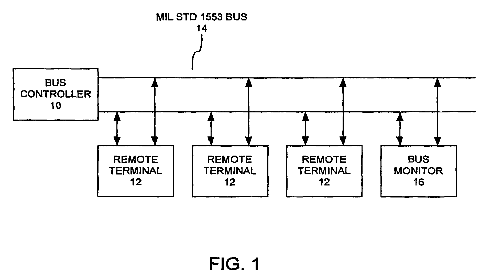
However recording all of the transactions on a busy data bus might be impractical, so a bus monitor 16 is often configured to record a subset of the transactions, based on some criteria provided by the application program.
As a result, signals sent down the bus 14 to this connector may propagate or reflect back along the bus 14 upon reaching the open connector, creating interference.
Thus, a one-to-more than one or a one-to-many connection topology is not compatible with the conventional 1553 system or its equivalents.

Method used


Image

  • System and method for making busses limited to a linear topology extensible to other topologies
  • System and method for making busses limited to a linear topology extensible to other topologies
  • System and method for making busses limited to a linear topology extensible to other topologies

Examples


Embodiment Construction

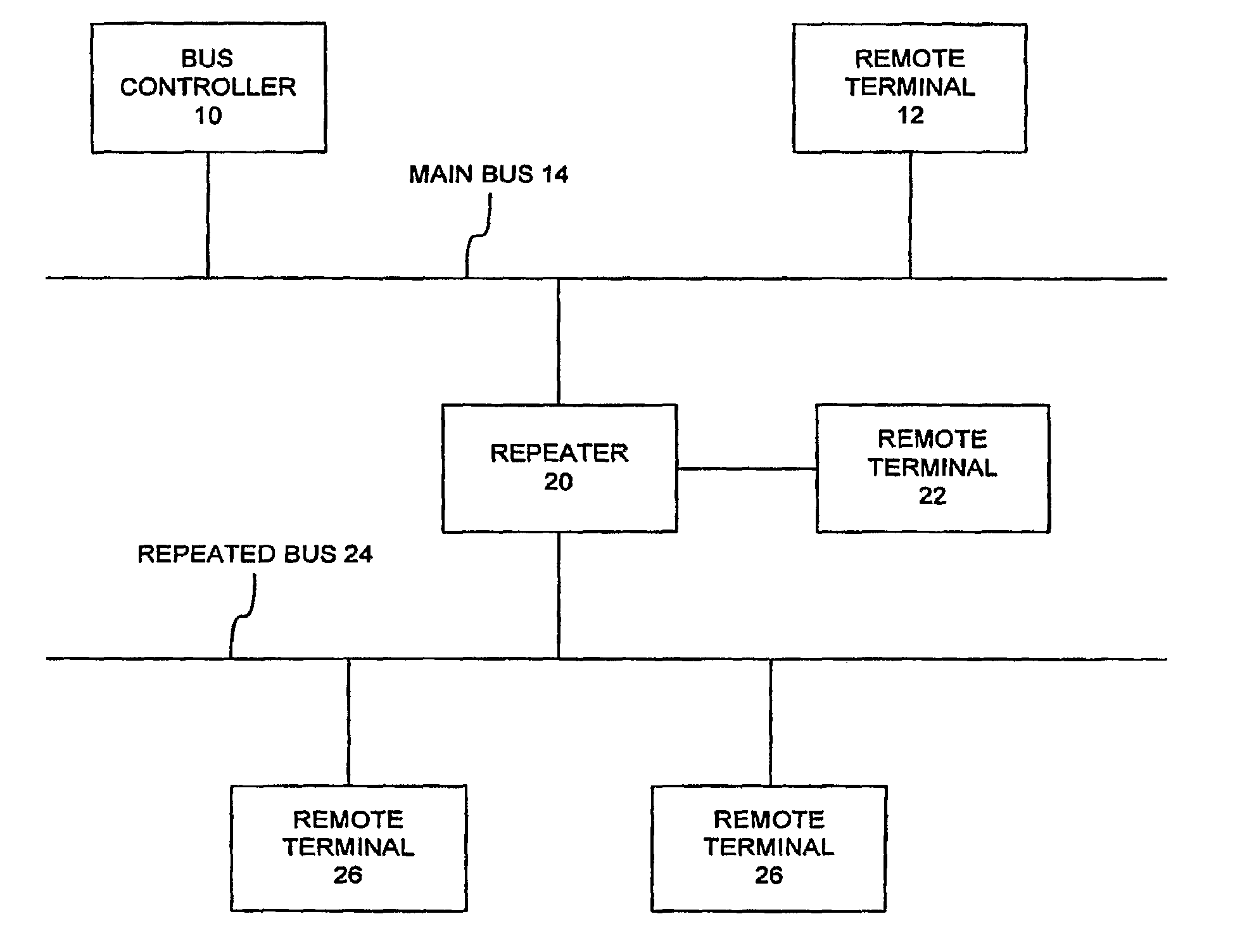
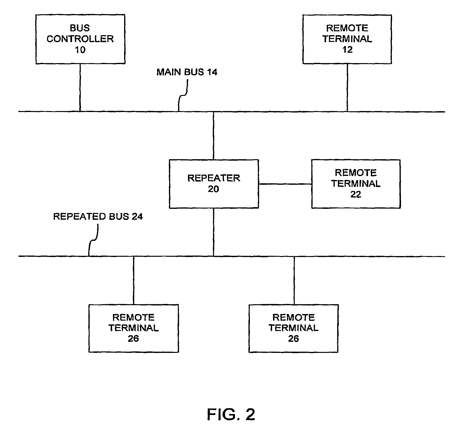
[0021]FIG. 2 is a block diagram of a bus system limited to a linear topology made extensible to a non-linear topology consistent with the present invention. As shown in FIG. 2, like the bus system of FIG. 1, a bus controller 10 and a remote terminal 12 are each coupled to a main bus 14. Although only a single remote terminal 12 is shown, it should be understood that several more remote terminals 12 can be coupled to the main bus 14. The main bus 14 is preferably configured in accordance with Mil-Std-1553, but can also be configured according to another standard that limits the configuration to a linear topology. In addition, other elements, such as a bus monitor (not shown), can also be coupled to the main bus 14.

[0022]As further shown in FIG. 2, a repeater 20 is also coupled to the main bus 14. The repeater 20 is transparent to the bus controller 10. When the main bus 14 is configured in accordance with Mil-Std-1553, each remote terminal is associated with a five-bit fixed address....


PUM


Abstract

A communication system and method includes a main bus that operates in accordance with a standard limited to a linear topology, a bus controller coupled to the main bus and configured to send and receive messages on the main bus, and a first remote terminal coupled to the main bus and configured to send and receive messages on the main bus including the messages sent by the bus controller. The system and method also includes a repeater coupled to the main bus and configured to send and receive messages on the main bus including the messages sent by the bus controller and by the first remote terminal, and second and third remote terminals coupled to the repeater, wherein the second and third remote terminals send and receive messages on the main bus via the repeater.

Description

CROSS-REFERENCE TO RELATED APPLICATIONS[0001]This is a national stage application under 35 U.S.C. §371 of prior-filed, co-pending International Application No. PCT / US2007 / 002748, filed Feb. 1, 2007, which claims the benefit of U.S. Provisional Application No. 60 / 743,208, filed Feb. 1, 2006.FIELD OF THE INVENTION[0002]The present invention relates generally to bus communication and, more particularly, to a system and method for making busses limited to a linear topology extensible to other topologies.BACKGROUND OF THE INVENTION[0003]MIL-STD-1553 is military standard published by the United States Department of Defense that defines the mechanical, electrical and functional characteristics of a serial data bus. It was originally designed for use with military avionics, but has also become commonly used in spacecraft on-board data handling (OBDH) subsystems, both military and civil. It features a dual redundant balanced line physical layer, a (differential) network interface, time divis...

Claims


Application Information

Patent Timeline
Patent Type & Authority Patents(United States)
IPC IPC(8): H04B3/36
CPCH04L12/4604H04L12/403H04L12/40013H04L12/40032H04B7/14H04L12/40
Inventor LASSINI, STEFANO A.WAITE, PATRICK G.HABENSCHUSS, MICHAEL S.VOOGT, MARY
Owner GE AVIATION SYST LLC
Learn More