
Bidirectionally operable/switchable pull cord mechanism for a window shade

a pull cord and bidirectional technology, applied in the direction of screens, doors/windows, constructions, etc., can solve the problem of unresolved risks and achieve the effect of effectively preventing the bead chain or the pull cord from tangling a child

Inactive Publication Date: 2013-10-01
ZHU XIANG RONG
View PDF38 Cites 18 Cited by
  • Summary
  • Abstract
  • Description
  • Claims
  • Application Information

AI Technical Summary

Benefits of technology

[0003]An objective of the present invention is to provide a bidirectionally operable / switchable pull cord mechanism for a window shade capable of effectively preventing the bead chain or pull cord from tangling a child.
[0008]To allow repeated smooth movement of the bead chain or pull cord, the handle is a sleeve including a hole having a shape of cross sections corresponding to that of the cross sections of the barrel.
[0009]To allow easy adjustment of the position of the positioning block, the link includes a channel in communication with the passageway. An actuating rod is received in the channel and connected to the positioning block. In use, the positioning block is moved to the desired position through the actuating rod.
[0013]To increase the sliding effect of the sleeve, the sleeve and the sliding block are made of plastic or aluminum alloy.
[0014]Compared to the current techniques, the present invention can effectively prevent the bead chain or pull cord from tangling a child.

Problems solved by technology

However, the bead chain or pull cord is soft and has two sections connected to the window shade, such that the bead chain or pull cord is liable to tangle the child by the neck and, thus, causes danger, which potential risk has not yet been effectively solved by now.

Method used


Image

  • Bidirectionally operable/switchable pull cord mechanism for a window shade
  • Bidirectionally operable/switchable pull cord mechanism for a window shade
  • Bidirectionally operable/switchable pull cord mechanism for a window shade

Examples


Embodiment Construction

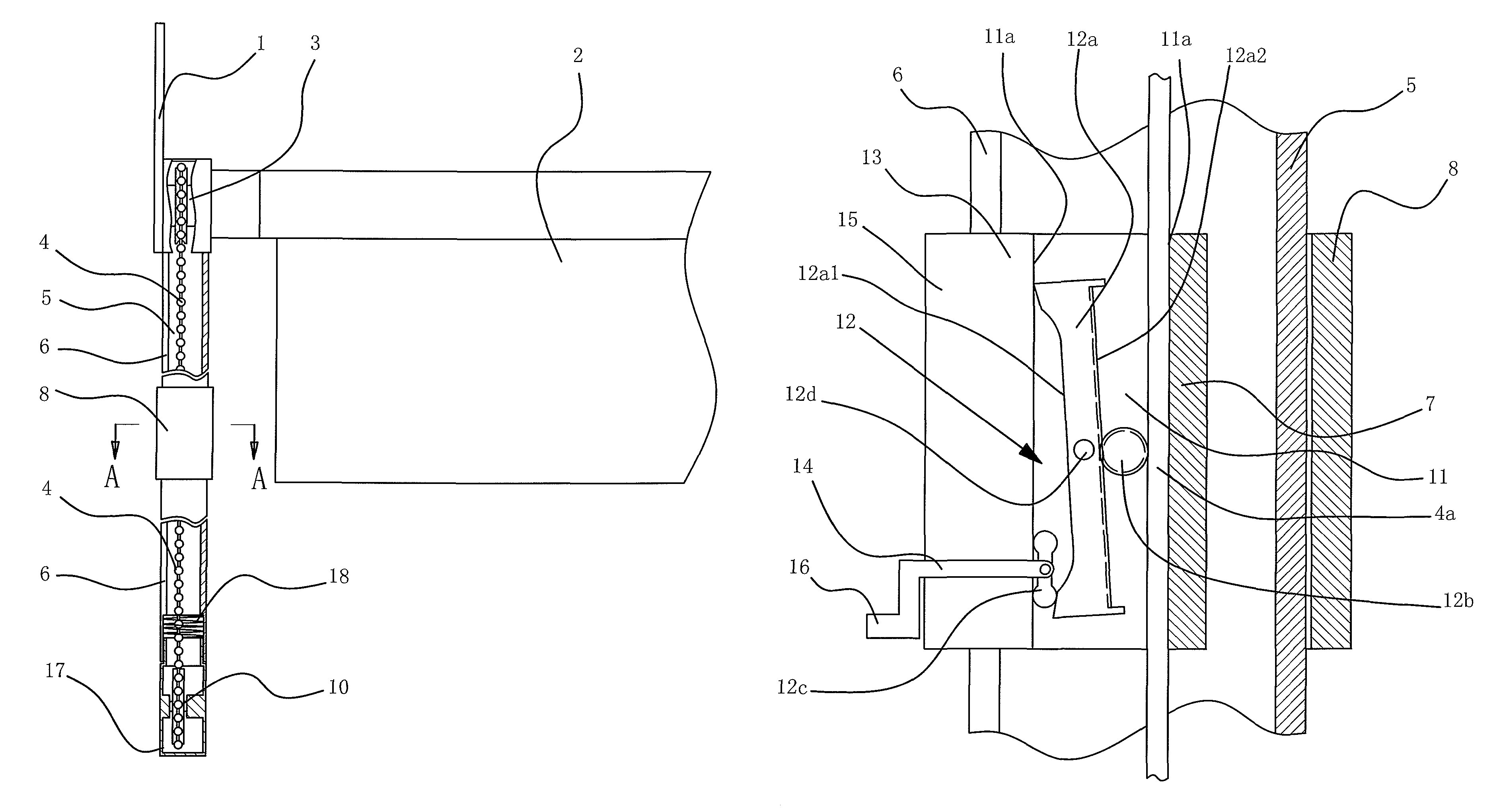
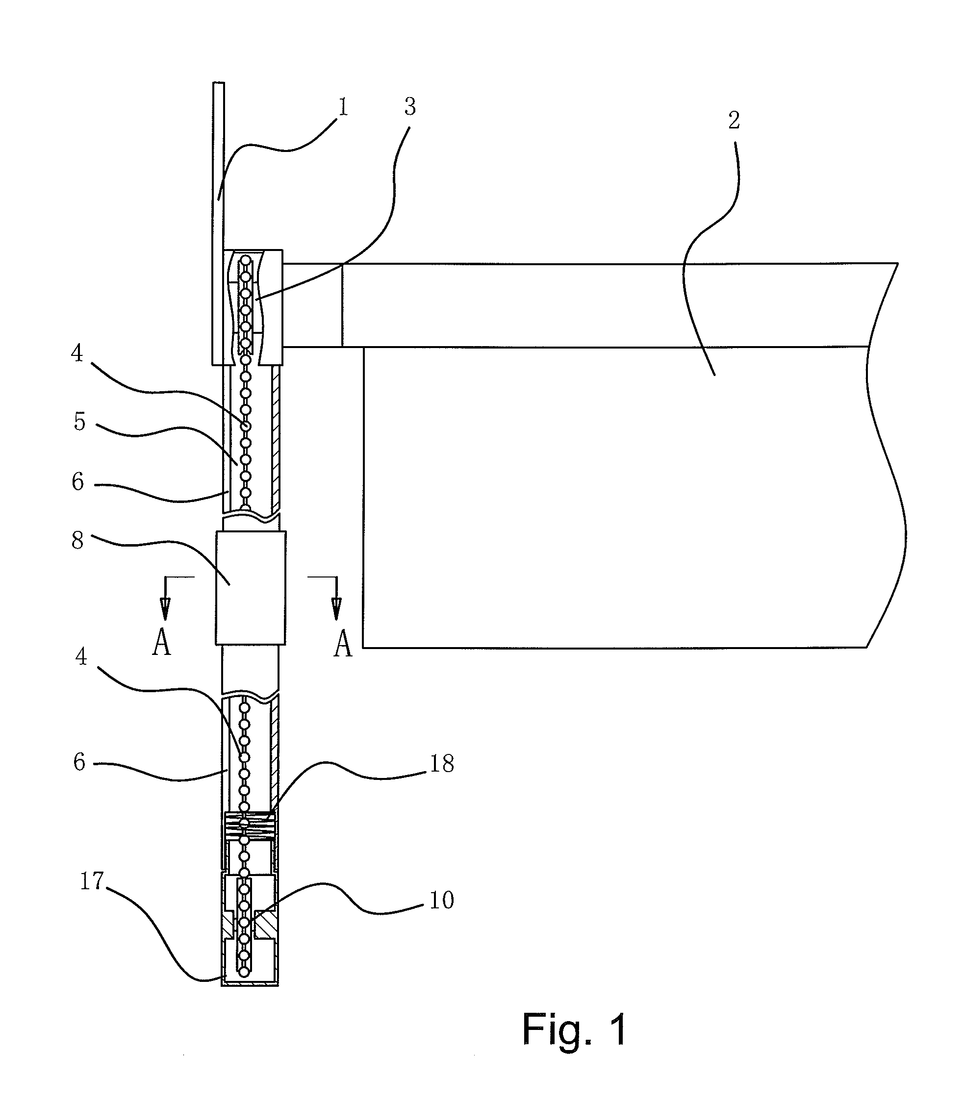
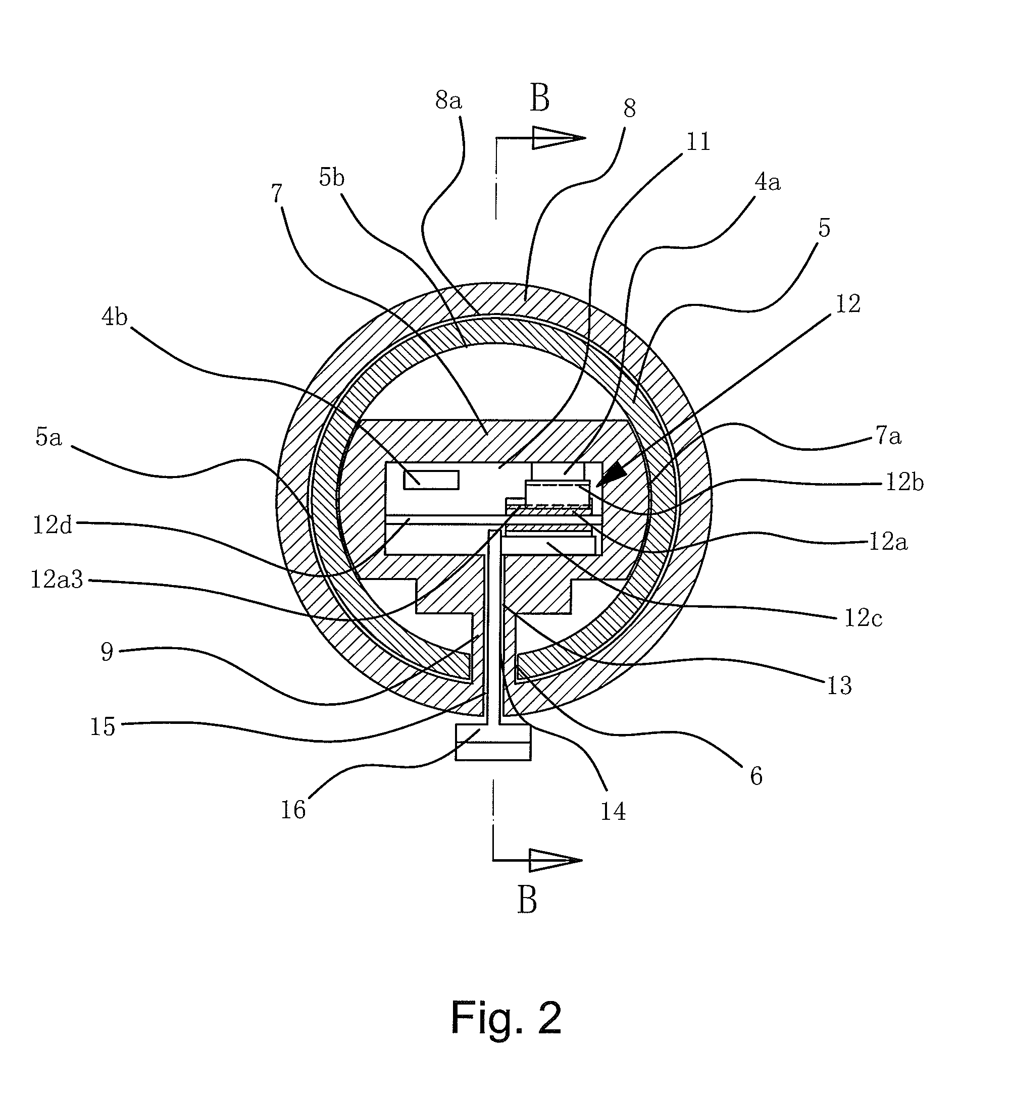
[0021]A pull cord mechanism for a window shade includes a frame 1, a shade 2, a shade driving mechanism 3, and an endless bead chain or pull cord 4 for driving the shade driving mechanism 3. The shade driving mechanism 3 is fixed to the frame 1 and drives the shade 2 to release / wind or to move in a horizontal direction. Particularly, a barrel 5 is mounted to the frame 1 at a location corresponding to the bead chain or pull cord 4. The barrel 5 includes a peripheral wall having a slit 6 extending in an axial direction. A sliding block 7 is slideably received in the barrel 5. A handle 8 is mounted outside of the barrel 5. The sliding block 7 is connected to the handle 8 by a link 9 extending through the slit 6. The bead chain or pull cord 4 is received in the barrel 5. A fixed pulley 10 is mounted to an end of the barrel 5. The bead chain or pull cord 4 is wound around the fixed pulley 10. The sliding block 7 includes a passageway 11 in an intermediate portion thereof. A follower devi...


PUM


Abstract

A pull cord mechanism for a window shade includes a frame (1), a shade (2), a shade driving mechanism (3), and a bead chain or pull cord (4) for driving the shade driving mechanism (3). A sliding block (7) is slideably received in a barrel (5) receiving the pull cord (4). A handle (8) is mounted outside of the barrel (5) and connected to the sliding block (7). A pivotal plate (12a) is pivotably supported in a passageway (11) of the sliding block (7). A recess is defined in one of a rear side (12a1) of the pivotal plate (12a) and a wall (11a) of the passageway (11) facing the rear side (12a1). A positioning block (12c) is located between the rear side (12a1) of the pivotal plate (12a) and the wall (11a) of the passageway (11). A gear (12b) is located between the section (4a) of the pull cord (4) and a front side (12a2) of the pivotal plate (12a) opposite to the rear side (12a1).

Description

BACKGROUND OF THE INVENTION[0001]The present invention relates to a pull cord mechanism for a window shade.[0002]The endless bead chains or pull cords of currently available pull cord mechanisms for driving the shade driving mechanisms to release / wind the window shades or to move the window shades in a horizontal direction are exposed. Driven by the playful nature, a child often plays the bead chain or pull cord as a toy. However, the bead chain or pull cord is soft and has two sections connected to the window shade, such that the bead chain or pull cord is liable to tangle the child by the neck and, thus, causes danger, which potential risk has not yet been effectively solved by now.BRIEF SUMMARY OF THE INVENTION[0003]An objective of the present invention is to provide a bidirectionally operable / switchable pull cord mechanism for a window shade capable of effectively preventing the bead chain or pull cord from tangling a child.[0004]The present invention fulfills the above objectiv...

Claims


Application Information

Patent Timeline
Patent Type & Authority Patents(United States)
IPC IPC(8): A47G5/02E06B9/56A47H1/00
CPCE06B9/326E06B9/56E06B2009/3222
Inventor ZHU, XIANG-RONG
Owner ZHU XIANG RONG
Learn More