Fluid pressure shock absorber

a shock absorber and flue gas technology, applied in the direction of shock absorbers, vibration dampers, dampers-spring combinations, etc., can solve the problems of difficult to securely prevent the main valve from being opened, unstable damping force, and difficult to stabilize the main valve opening, so as to improve the durability of the shock absorber and stabilize the damping force

Active Publication Date: 2013-10-01
HITACHI LTD
View PDF11 Cites 12 Cited by
  • Summary
  • Abstract
  • Description
  • Claims
  • Application Information

AI Technical Summary

Benefits of technology

[0007]The present invention has been contrived in consideration of the above-mentioned circumstances, and an object thereof is to provide a fluid pressure shock absorber in which it is possible to generate a stable damping force and improve durability of the shock absorber.

Problems solved by technology

However, the hydraulic shock absorber disclosed in Japanese Patent Application Public Disclosure No. 2005-344911 remains subject to the following problems.
Namely, because it is not possible to adequately increase a pressure in the backpressure chamber by a pressure introduced through the check valve when the piston is in an ultra low speed range, it is difficult to securely prevent the main valve from being opened, whereby a damping force is liable to become unstable.
In addition, the extension-side and compression-side backpressure chambers are pressurized during both of extension and compression strokes, with the consequence that loads are repeatedly applied to the main valves, whereby durability of the main valves deteriorates.

Method used


Image

  • Fluid pressure shock absorber
  • Fluid pressure shock absorber
  • Fluid pressure shock absorber

Examples


first embodiment

[0035]Next, an operation of the first embodiment configured as described above will be discussed.

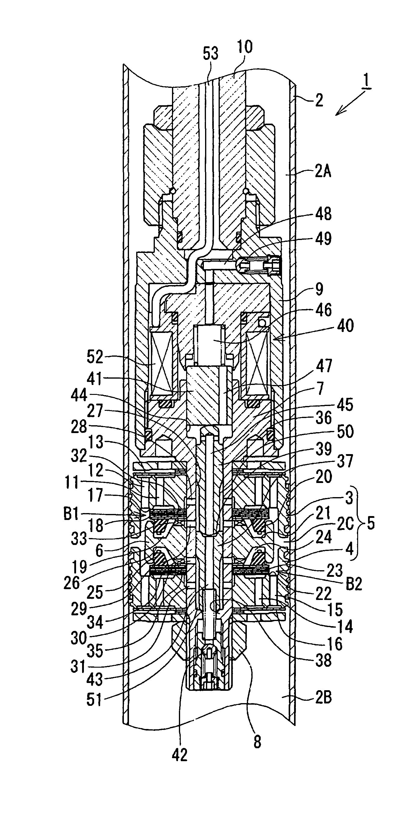
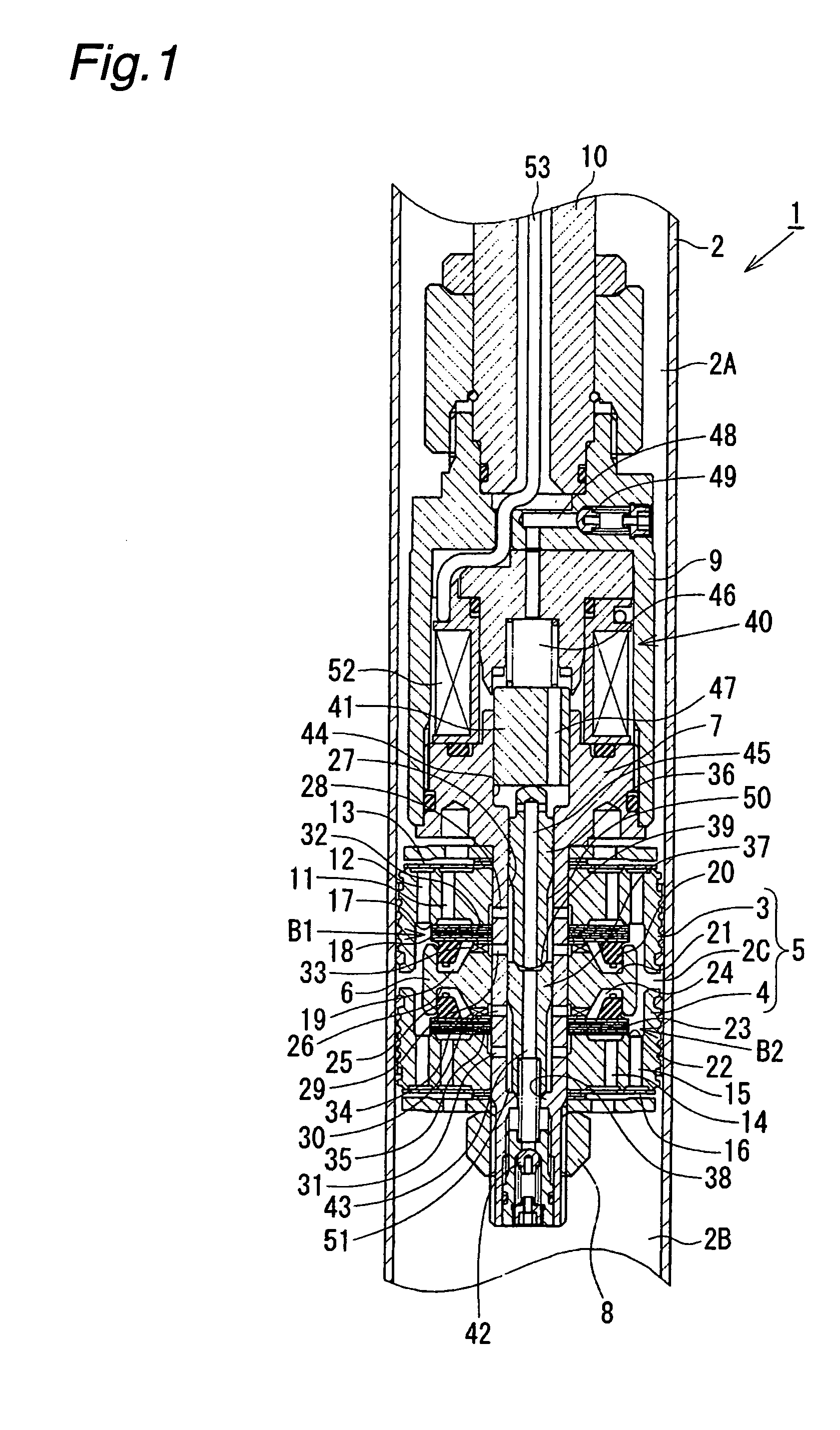
[0036]During an extension stroke of the piston rod 10, until the extension-side main valve 18 is opened, oil of the cylinder upper chamber 2A side flows through the extension-side oil passage 11, the orifice oil passage 32, the port 28 and the annular chamber 50, opens the extension-side valve body 36, and then flows through the communication passage 43 and the check valve 42 into the cylinder lower chamber 2B. At this time, a pressure of the annular chamber 50 is introduced into the extension-side backpressure chamber 19 through the port 29 and the oil passage 33. Once the pressure of the cylinder upper chamber 2A side reaches a valve-opening pressure of the extension-side main valve 18, the main valve 18 is opened and then the oil of the extension-side oil passage 11 starts to flow through the piston chamber 2C and the oil passage 15 of the second piston 4, and opens the extension-side...

third embodiment

[0052]As shown in FIG. 3, in a damping force adjustable hydraulic shock absorber 61 of the third embodiment, extension-side and compression-side backpressure chambers 19 and 24 are in communication with each other through an oil passage 62 provided in a valve member 6, and are further in communication with a guide bore 27 through a common port 63. A single valve body 64, which is a common valve shared by the extension-side and the compression-side, is fitted in the guide bore 27. While a back end side of the valve body 64 is configured to be fitted in the guide bore 27, a front end side of the valve body 64 has a smaller diameter than that of the back end side, whereby an annular chamber 65 in communication with the port 63 is defined between the valve body 64 and a side wall of the guide bore 27, and a pressure receiving surface which receives a pressure of the annular chamber 65 is formed on the front end side of the valve body 64. When the front end of the valve body 64 moves awa...


PUM


Abstract

A fluid pressure shock absorber in which valve opening of the main valve is controlled by an inner pressure of a backpressure chamber. A first piston (3) and a second piston (4) coupled to a piston rod (10) are fitted in a cylinder (2) such that a piston chamber (2C) is defined between the first and second pistons. An extension-side main valve (18) and a compression-side main valve (23) are provided in the piston chamber (2C). Valve opening of the main valves is controlled by an extension-side backpressure chamber (19) and a compression-side backpressure chamber (24). A compression-side check valve (13) and an extension-side check valve (16) are provided at the first piston (3) and the second piston (4). During an extension stroke of the piston rod (10), the compression-side check valve (13) is closed, whereby action of a pressure of a cylinder upper chamber (2A) on the compression-side main valve (23) is prevented. During a compression stroke of the piston rod (10), the extension-side check valve (16) is closed, whereby action of a pressure of a cylinder lower chamber (2B) on the extension-side main valve (18) is prevented. Accordingly, it is possible to generate a stable damping force, and enhance durability of the extension-side main valve (18) and the compression-side main valve (23).

Description

BACKGROUND OF THE INVENTION[0001]The present invention relates to a fluid pressure shock absorber such as a hydraulic shock absorber mounted on a suspension apparatus of a vehicle such as an automobile. In particular, the present invention relates to a fluid pressure shock absorber including a backpressure chamber for controlling a valve-opening pressure of a main valve which generates a damping force.[0002]Generally, a cylindrical hydraulic shock absorber mounted on a suspension apparatus of a vehicle such as an automobile comprises a sealed cylinder in which oil is contained, a piston rod, a piston coupled to the piston rod and slidably fitted in the cylinder, and a damping force generating mechanism provided at a piston portion, the damping force generating mechanism comprising an orifice, a disk valve and the like. In the hydraulic shock absorber configured as above, an extension or compression movement of the piston rod causes a sliding movement of the piston in the cylinder wh...

Claims


Application Information

Patent Timeline
Patent Type & Authority Patents(United States)
IPC IPC(8): F16F9/48
CPCF16F9/465F16F9/3485F16F9/32F16F9/34
Inventor YAMAGUCHI, HIROYUKIKATAYAMA, YOHEIHAYAMA, HIROYUKINEZU, TAKASHI
Owner HITACHI LTD
Why Eureka
Try Eureka