Dental implant system

a dental implant and abutment technology, applied in dental implants, dental surgery, medical science, etc., can solve the problems of abutment avulsion, less predictable solutions of conventional implants, and avulsion of conventional implants,

Inactive Publication Date: 2013-10-01
CHERKINSKY JORDAN MICHAEL +1
View PDF22 Cites 6 Cited by
  • Summary
  • Abstract
  • Description
  • Claims
  • Application Information

AI Technical Summary

Benefits of technology

[0006]In another aspect of the present invention, an implant system comprises an implant body having an hollow abutment cavity formed therein; implant body threads formed about an exterior portion of the implant body; implant body extension slots formed longitudinally in a lower portion of the implant body; implant body male threads formed on a top end of the implant body; an insert adapted to fit into the hollow abutment cavity, the insert having insert extensions configured to protrude through the implant body extension slots; an abutment having female threads to mate with the implant body male threads; a chamfer body line formed below the implant body male threads, where the abutment seals against the chamfer body line when the abutment female threads are engaged with the implant body male threads; an abutment hexagonal recess for wrench access formed in a top portion of the abutment; an abutment threaded convenience channel formed through the abutment; and an insert threaded convenience channel formed into the insert from a coronal face thereof, the insert threaded convenience channel aligning with the abutment threaded convenience channel.

Problems solved by technology

Conventional implants have less predictable solutions to resist rotation and lateral forces.
With conventional implants, there are no provisions to extend a crown or a custom abutment onto the implant body, therefore the lateral or rotational forces can result in avulsion of the implant abutment.
This may be the result of a broken or loosened screw, and quite possibly a fractured implant body.
Conventional implants also do not have predictable solutions to prevent sepsis at the interface of the abutment and the implant body.

Method used


Image

  • Dental implant system
  • Dental implant system
  • Dental implant system

Examples


Embodiment Construction

[0025]The following detailed description is of the best currently contemplated modes of carrying out exemplary embodiments of the invention. The description is not to be taken in a limiting sense, but is made merely for the purpose of illustrating the general principles of the invention, since the scope of the invention is best defined by the appended claims.

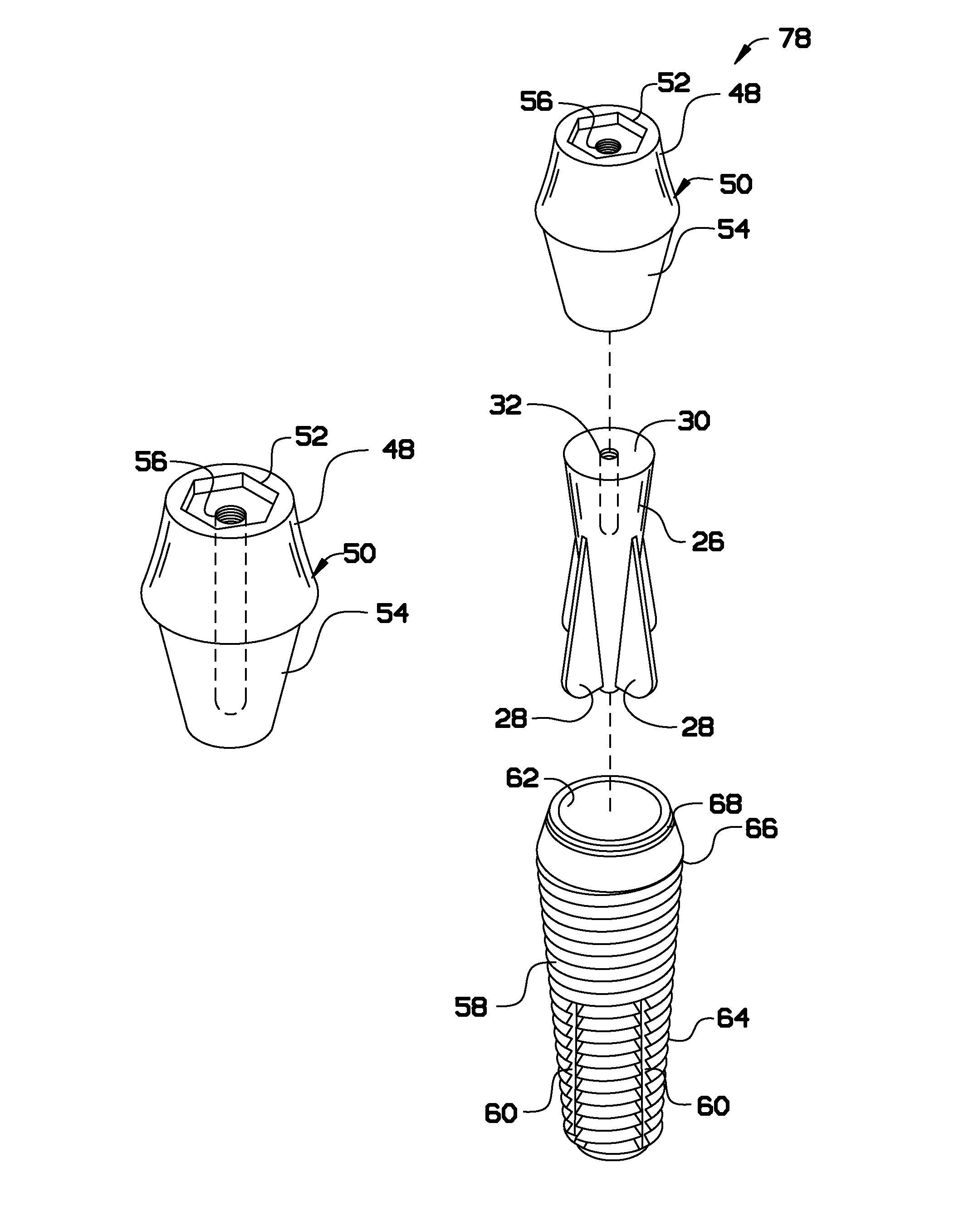
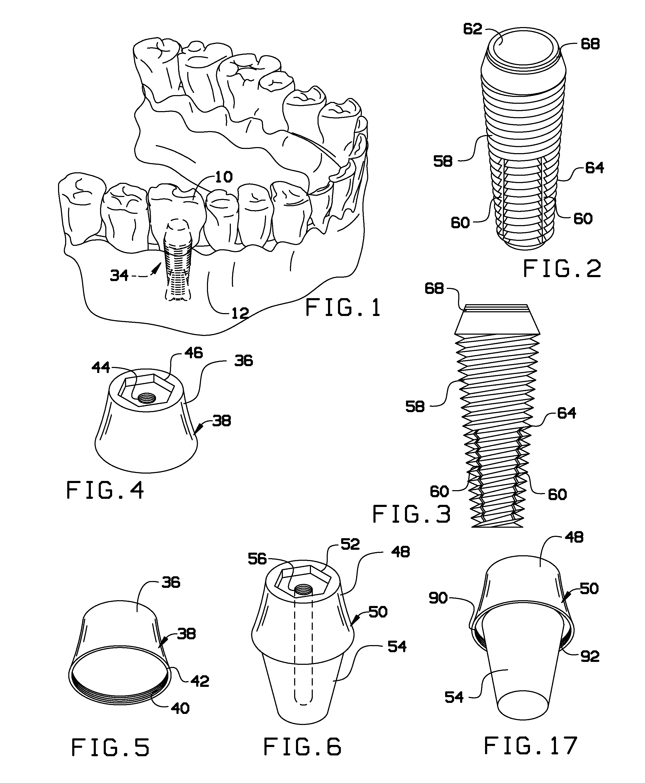
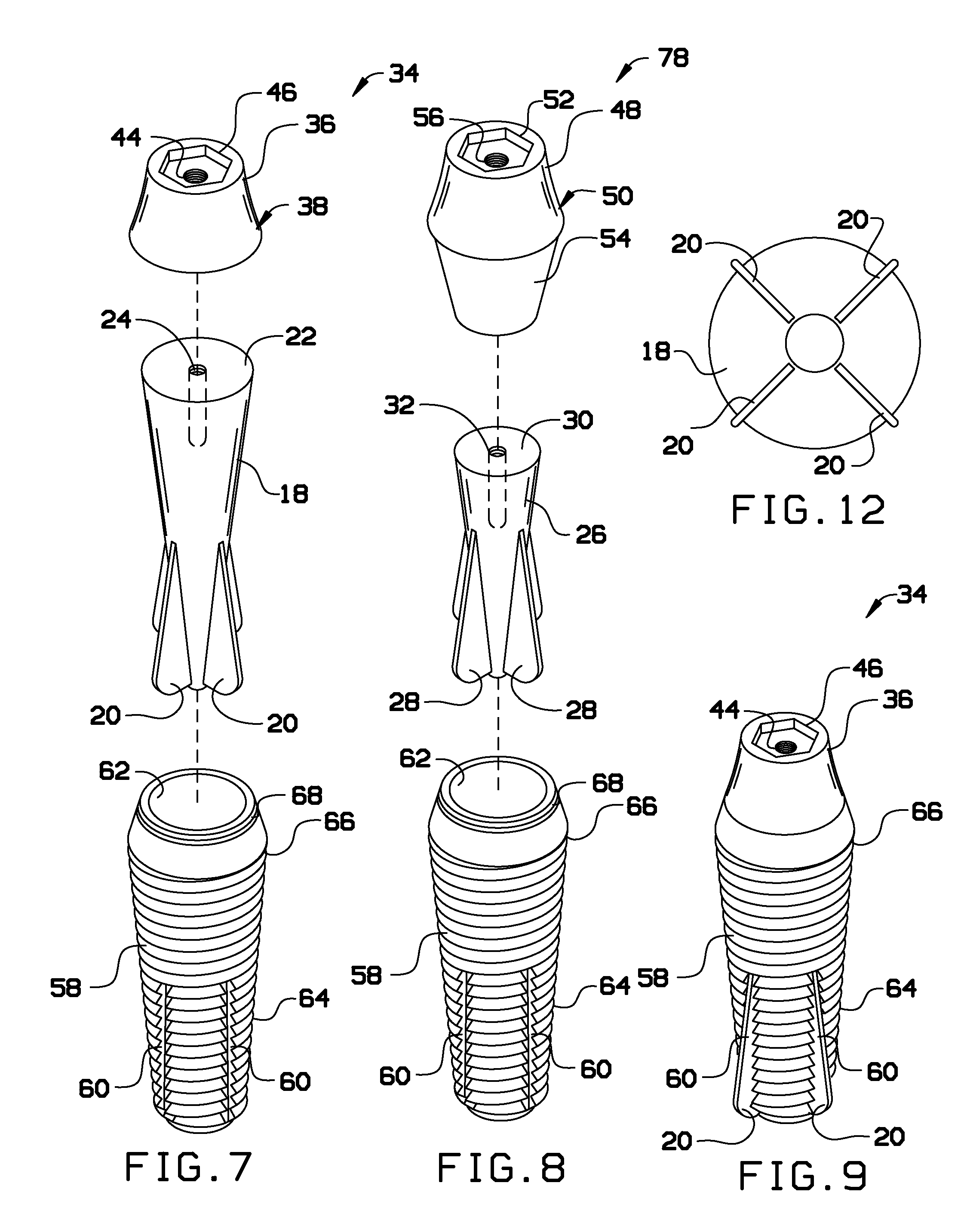
[0026]Broadly, an embodiment of the present invention provides a dental implant system that is hermetically sealed and uses an extruded extension retention design. The implant system provides additional retention and resistance to rotational and lateral forces and disperses these forces vertically and apically through the implant body. The implant system also provides protection from issues of sepsis at the junction between the abutment and the implant body, which can result in significant bone loss in conventional designs. The implant system integrates / unifies the components to result in a closer approximation to a natural toot...


PUM


Abstract

A dental implant system is hermetically sealed and uses a radially extruded extension retentive design. The implant system provides additional retention and resistance to rotational and lateral forces and disperses these forces vertically and apically through the implant body. The implant system also provides protection from issues of sepsis at the junction between the abutment and the implant body, when can result in significant bone loss in conventional designs. The implant system integrates/unifies the components to result in a closer approximation to a natural tooth root to improve resistance to lateral and rotational forces that challenge the integrity of conventional implants. The implant system provides a shorter average length in proportion to its retentive surface area, thereby effectively reducing the needed length to avoid invading nearby anatomic structures, such as the maxillary sinus, mental foramen and/or mandibular canal.

Description

CROSS-REFERENCE TO RELATED APPLICATIONS[0001]This application claims the benefit of priority of U.S. provisional patent application No. 61 / 665,889, filed Jun. 28, 2012, the contents of which are herein incorporated by reference.BACKGROUND OF THE INVENTION[0002]The present invention relates to dental implant systems and, more particularly, to a three-component dental implant system that is hermetically sealed and uses an extruded extension retention design.[0003]Conventional implants have less predictable solutions to resist rotation and lateral forces. The distribution of forces is relied upon to be borne by a diminutive screw in concert with an internal butt joint design that does not reliably direct the forces apically. With conventional implants, there are no provisions to extend a crown or a custom abutment onto the implant body, therefore the lateral or rotational forces can result in avulsion of the implant abutment. This may be the result of a broken or loosened screw, and qu...

Claims


Application Information

Patent Timeline
Patent Type & Authority Patents(United States)
IPC IPC(8): A61C8/00
CPCA61C8/0033A61C8/0068A61C8/0069A61C8/0074A61C8/0019
Inventor CHERKINSKY, JORDAN MICHAELKILMAN, STANLEY MYRON
Owner CHERKINSKY JORDAN MICHAEL
Why Eureka
Try Eureka