Electrical busway plug-in unit with improved restraint mechanism

a plug-in unit and electric busway technology, applied in the direction of connection contact member materials, laminated bus-bars, coupling device connections, etc., can solve the problems of reducing the allowable density of plug-in units on the busway, increasing the overall envelope size,

Inactive Publication Date: 2013-10-01
SCHNEIDER ELECTRIC USA INC
View PDF20 Cites 5 Cited by
  • Summary
  • Abstract
  • Description
  • Claims
  • Application Information

AI Technical Summary

Benefits of technology

[0004]The present invention permits the density of plug-in units on electrical busways to be significantly increased by providing plug-in units with an improved restraint mechanism that extends through the body of the plug-in unit. This not only reduces the overall envelope size of each plug-in unit, but also permits the plug-in units to be installed closely adjacent each other on the busway with little or no space between adjacent units.
[0005]In one embodiment, the restraint mechanism does not require the use of any hand tools, and permits an installer to attach a plug-in unit to a busway by simply turning a pair of knobs on the front panel of the plug-in unit. Thus, the installation process is greatly simplified, which in turn reduces the time required to install each plug-in unit.
[0010]The front wall of the housing may be a detachable front panel, with the knob being secured to the front panel and slidably mounted on the shaft so that the knob can be removed from the shaft along with the front panel without affecting the securement of the plug-in unit to the housing.

Problems solved by technology

These attachment mechanisms increase the overall envelope size of each plug-in unit, which in turn reduces the allowable density of plug-in units on the busway.

Method used


Image

  • Electrical busway plug-in unit with improved restraint mechanism
  • Electrical busway plug-in unit with improved restraint mechanism
  • Electrical busway plug-in unit with improved restraint mechanism

Examples


Embodiment Construction

[0019]Although the invention will be described in connection with certain aspects and / or embodiments, it will be understood that the invention is not limited to those particular aspects and / or embodiments. On the contrary, the invention is intended to cover all alternatives, modifications, and equivalent arrangements as may be included within the spirit and scope of the invention as defined by the appended claims.

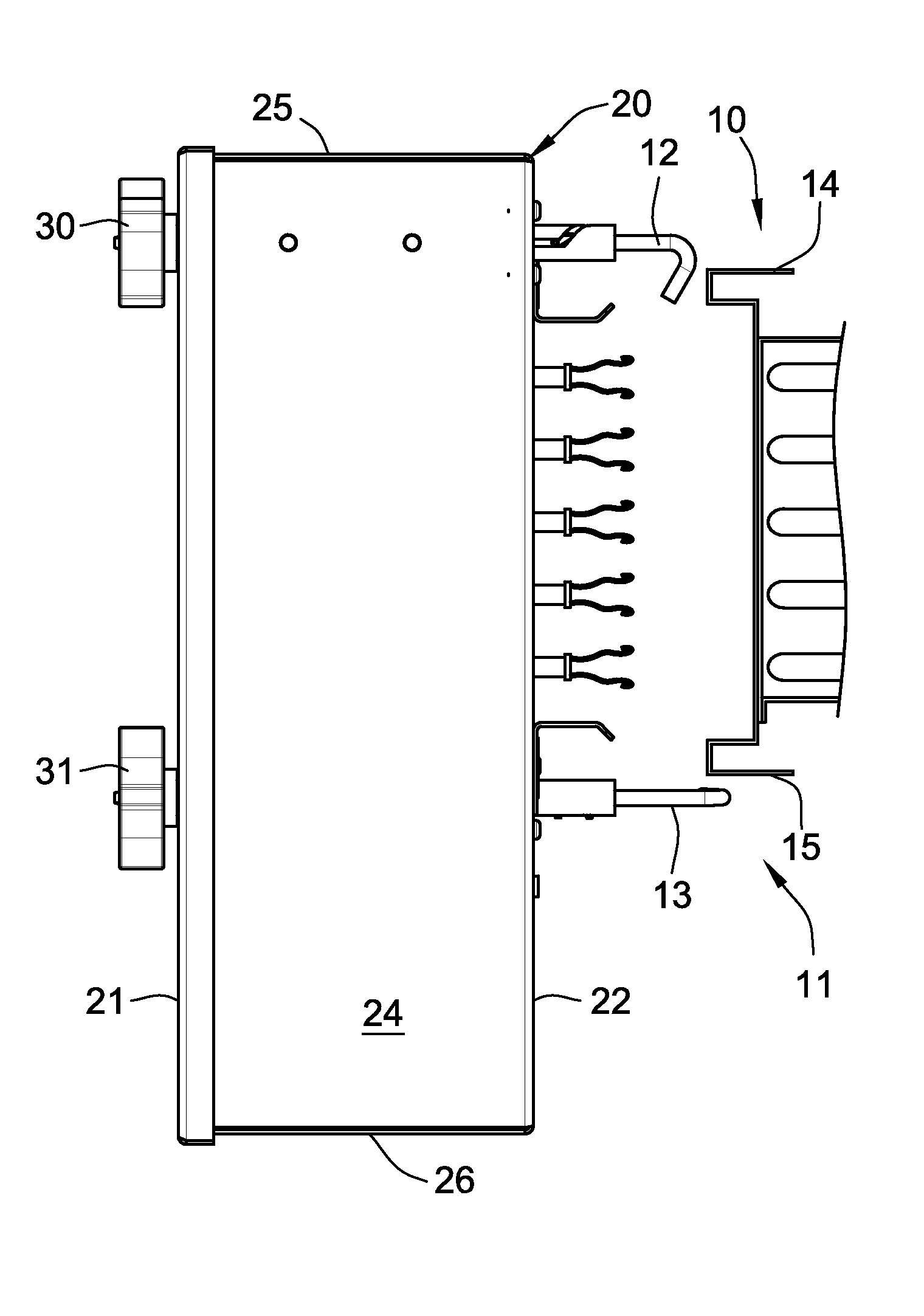
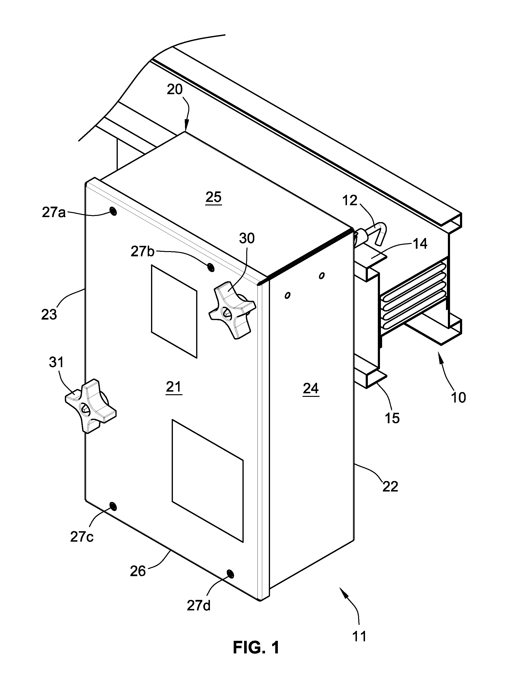
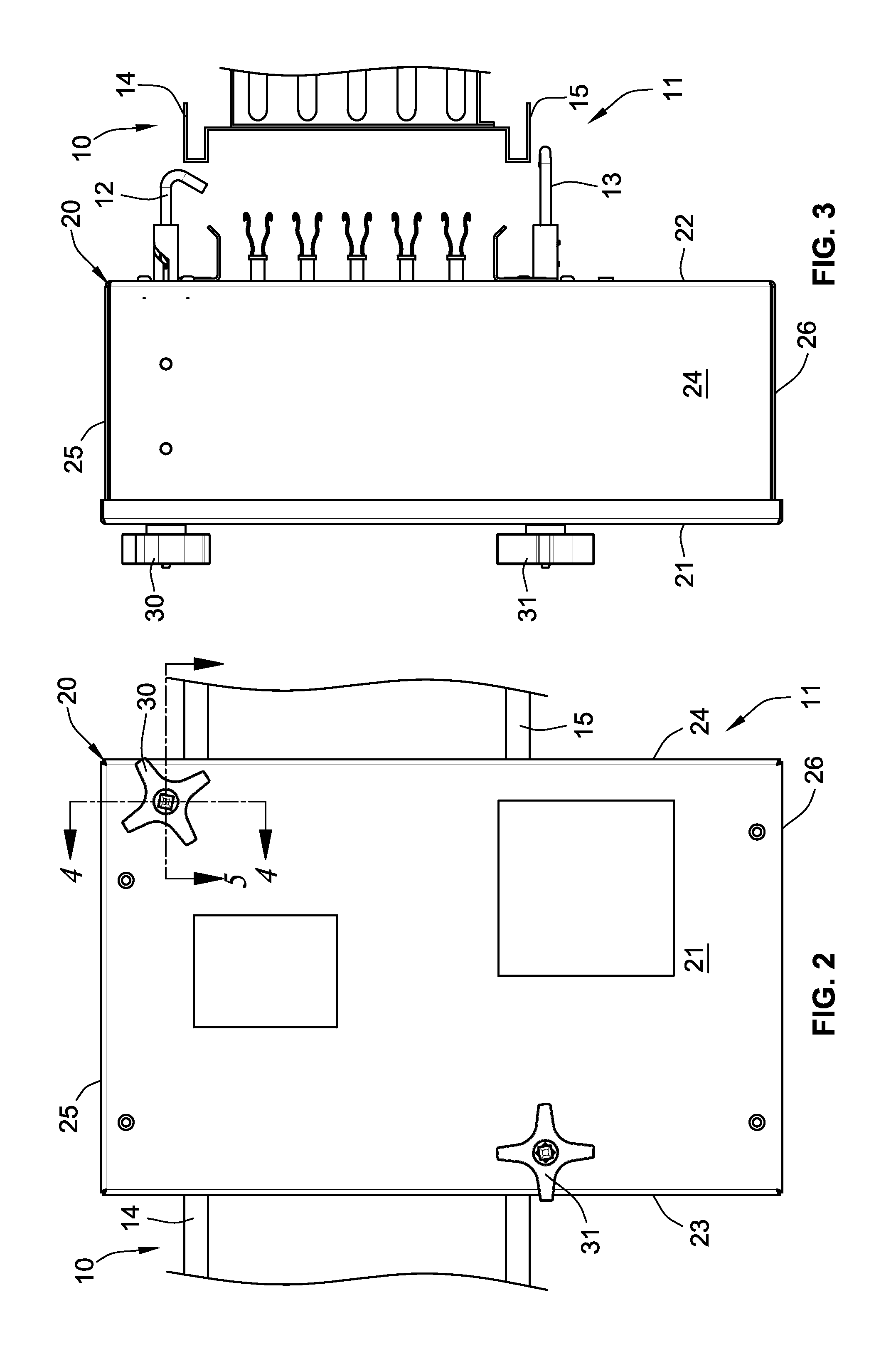
[0020]Turning now to the drawings, FIG. 1 includes a partial illustration of a conventional plug-in electrical busway 10 for use in distributing electrical power and having a pair of outside flanged walls. This particular example is the “I-Line II” busway made and sold by Schneider Electric, but a variety of different busways are commercially available, both from Schneider Electric and from other manufacturers. One other example is the “Powerbus” plug-in busway made and sold by Schneider Electric, which has longitudinal flanges extending upwardly from the center of the top ...


PUM


Abstract

An electrical busway plug-in unit includes a pair of restraint mechanisms extending through the housing of the plug-in unit for mechanically attaching the plug-in unit to the busway. Each restraint mechanism includes a rotatable shaft extending through the front wall of the housing, and a knob attached to the front end of the shaft, on the exterior side of the front wall of the housing, for manually rotating the shaft. A mechanical connector projects rearwardly from the rear wall of the housing and extends forwardly into the interior of the housing where the connector is coupled to the shaft so that rotational movement of the shaft in opposite directions moves the connector into and out of latching engagement with the busway.

Description

FIELD OF THE INVENTION[0001]The present invention relates generally to plug-in units for electrical busways for electrical power distribution and, more particularly, to an improved restraint mechanism for such plug-in units.BACKGROUND OF THE INVENTION[0002]Busways for electrical distribution systems are commonly understood in the art to include multiple pre-assembled sections of a duct containing individually insulated, usually flat electrical conductors or busbars. The individual sections are designed to be easily connected, both electrically and mechanically, end-to-end to form any desired length. In a plug-in busway, at least some of the sections are equipped with built-in electrical receptacles adapted to receive plug-in units containing electrical equipment to be connected to the busway, such as circuit breakers and different kinds of switches and control devices. To ensure the integrity of the electrical connections between the plug-in units and the busway, and to protect the ...

Claims


Application Information

Patent Timeline
Patent Type & Authority Patents(United States)
IPC IPC(8): H01R4/60
CPCH01R25/145H01R13/623H02G5/04H02G5/08H02G5/005
Inventor DOZIER, STEVEN WAYNE
Owner SCHNEIDER ELECTRIC USA INC
Why Eureka
Try Eureka