Method and system for manufacturing sintered rare-earth magnet having magnetic anisotropy
a rare-earth magnet, anisotropy technology, applied in the direction of magnetic materials, magnetic bodies, printing, etc., can solve the problems of reducing the maximum energy product, lowering the saturation magnetization, and the method is inferior to the sintering method in both magnetic characteristics and productivity, and achieves low oxygen content, high coercive force, and small
- Summary
- Abstract
- Description
- Claims
- Application Information
AI Technical Summary
Benefits of technology
Problems solved by technology
Method used
Image

Examples
embodiments
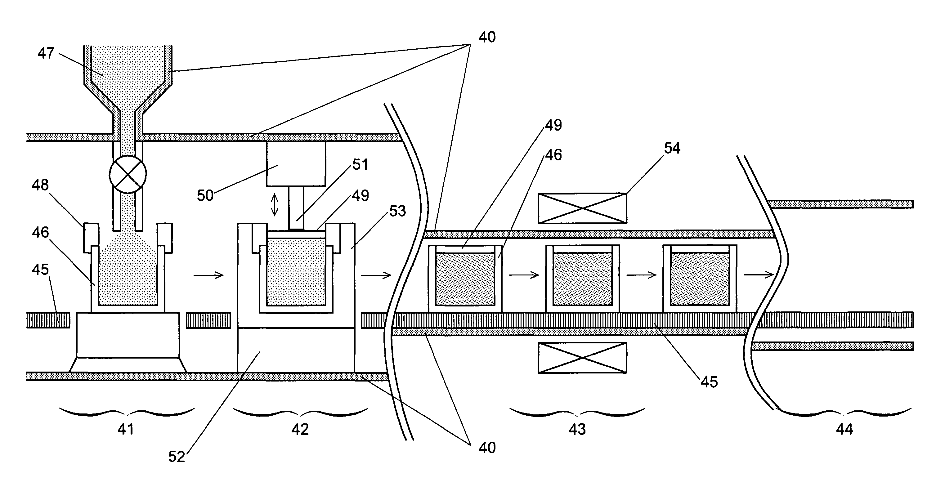
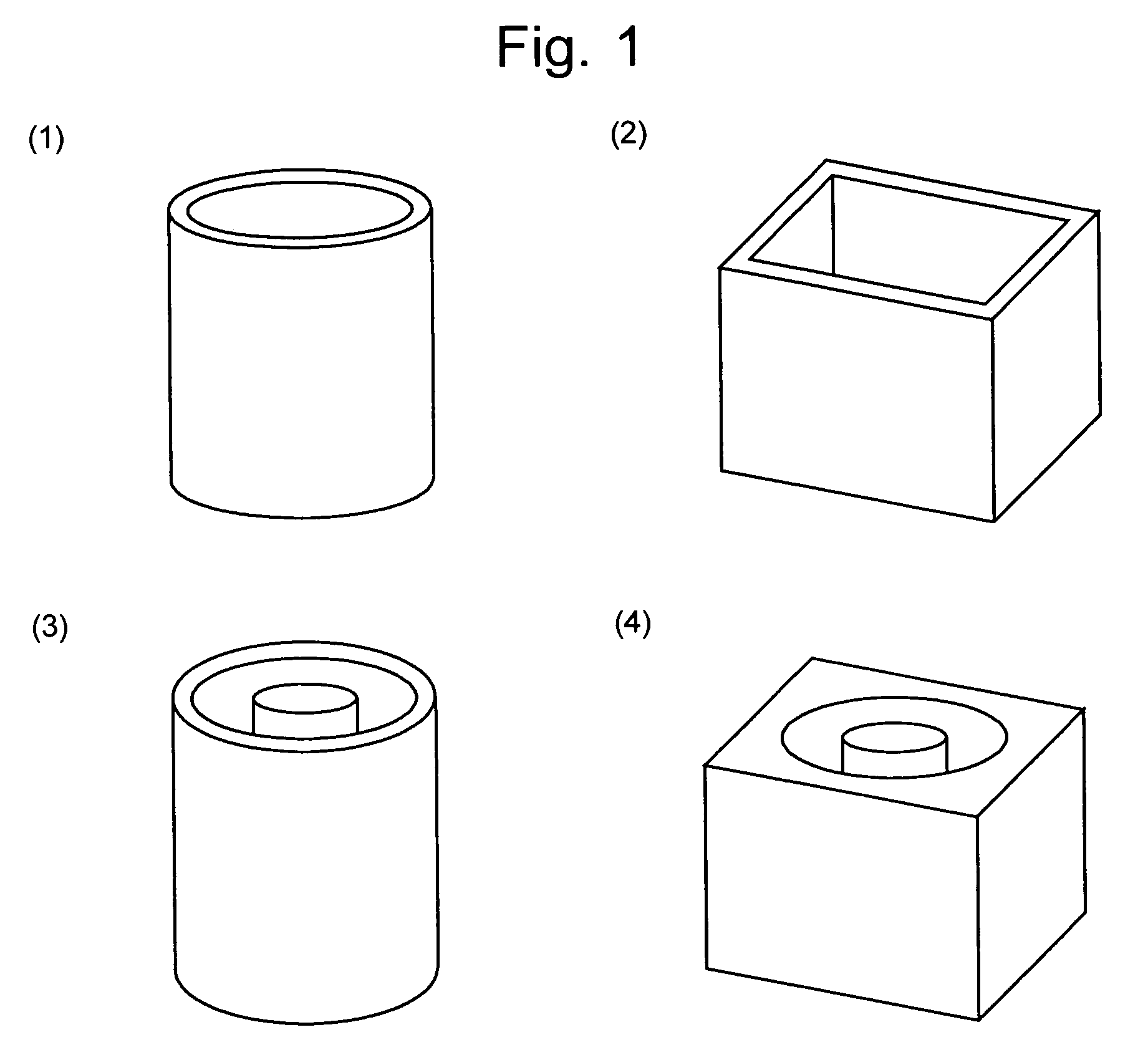
[0217][Mold]
[0218]Preferably, the mold should be made of a material that can withstand the high sintering temperature (up to 1100 degrees Celsius). In the course of pre-heating the mold, the particles loosely combine with each other, whereby the object to be sintered becomes able to sustain its shape. In this preliminary sintered state, a portion or the entirety of the mold can be removed so that the preliminary sintered body can be set into another mold or onto a bedplate. The preliminary sintering temperature is preferably from 500 degrees Celsius to a level that is 30 degrees Celsius lower than the sintering temperature. The mold used in the preliminary sintering process can be made of any material that withstands the above temperature range.
[0219]Examples of the mold material include iron, iron alloy, stainless steel, permalloy, heat resisting steel, heat resisting alloy and superalloy; molybdenum, tungsten and their alloy; and ferrite, alumina and other ceramics.
[0220][Coating ...
first experiment
[0259]An alloy containing, in weight percent, 31.5% of Nd, 0.97% of B, 0.92% of Co, 0.10% of Cu and 0.26% of Al with the remaining percentage being Fe was prepared by a strip-casting method. This alloy was crushed into flakes of 5 to 10 mm in size, which were subjected to hydrogen pulverization and jet-milling processes to obtain a fine powder having a grain size of D50=4.9 μm. The above processes were performed under atmosphere with an oxygen concentration of not more than 0.1% in order to reduce the amount of oxygen in the fine powder to the lowest possible level. After the jet-mill pulverization, a liquid lubricant of methyl caproate was added to the powder by 0.5 weight percent, and the mixture was stirred by a mixer.
[0260]The powder was loaded into stainless pipes each having an inner diameter of 10 mm, an outer diameter of 12 mm and a length of 30 mm, with powder-loading density of 3.0, 3.2, 3.4, 3.6, 3.8 and 4.0 g / cm3, respectively. Then, a stainless cover was attached to eac...
second experiment
[0261]This experiment focused on the dependency of the shape and density of the sintered body on the mold material (or saturation magnetization Js). The same alloy as used in the first experiment was subjected to hydrogen pulverization and jet-milling processes to obtain two kinds of fine powders having grain sizes of D50=4.9 μm and D50=2.9 μm, respectively. The mold cavity into which the powder was to be loaded was shaped like a short cylinder of 25 mm in diameter and 7 mm in thickness. The molds were created from different materials: iron (Js=2.15 T), permalloy (Js=1.4 T, 1.35 T, 0.73 T, 0.65 T and 0.50 T), and nonmagnetic stainless steel. All of these molds had a wall thickness of 1 mm.
[0262]The powder was loaded into the cavity of each mold with a loading density of 3.8 g / cm3. The same pulsed magnetic field as used in the first experiment, consisting of the AC, DC and DC pulses, each pulse having a peak value of 8 T, was applied to the powder held in each mold to orient the powd...
PUM
| Property | Measurement | Unit |
|---|---|---|
| grain size D50 | aaaaa | aaaaa |
| magnetic field | aaaaa | aaaaa |
| magnetic field | aaaaa | aaaaa |
Abstract
Description
Claims
Application Information
 - R&D
- Intellectual Property
- Life Sciences
- Materials
- Tech Scout
- Unparalleled Data Quality
- Higher Quality Content
- 60% Fewer Hallucinations
Browse by: Latest US Patents, China's latest patents, Technical Efficacy Thesaurus, Application Domain, Technology Topic, Popular Technical Reports.
© 2025 PatSnap. All rights reserved.Legal|Privacy policy|Modern Slavery Act Transparency Statement|Sitemap|About US| Contact US: help@patsnap.com