Optical fiber cable and optical fiber ribbon

a technology of optical fiber ribbon and optical fiber, which is applied in the direction of optics, fibre mechanical structures, instruments, etc., can solve the problems of deteriorating connection efficiency, insufficient space for additionally laying optical fiber cables, and difficulty in bending optical fiber ribbons in a width direction from the shape, so as to reduce warping, reduce optical loss, and achieve high connection efficiency

Active Publication Date: 2013-10-01
NIPPON TELEGRAPH & TELEPHONE CORP
View PDF15 Cites 286 Cited by
  • Summary
  • Abstract
  • Description
  • Claims
  • Application Information

AI Technical Summary

Benefits of technology

[0038]The optical fiber cable according to the present invention can maintain a stable optical loss characteristic with respect to the external force applied during use, in the mounting density of the cable core portion that is almost equal to that of the optical fiber cable using the mono-coated optical fibers, reduce the warping applied to the optical fiber with respect to the cable bending, and secure sufficient long-term reliability. Since collective connection using the optical fiber ribbons is enabled, the optical fiber cable according to the invention has an effect that connection efficiency is high. Furthermore, it has an effect that identification or extraction of a desired optical fiber is superior, and single fiber separability at the time of intermediate post branching is superior.
[0039]In the optical ribbon according to the invention, the connecting portion that connect the adjacent mono-coated optical fibers are configured to have the thickness and the length in which the connecting portion can be easily buckled with respect to the external force applied in the width direction of the optical fiber ribbon, thereby, the connecting portion is easily buckled with respect to the external force applied in the width direction of the optical fiber ribbon. Therefore, bending anisotropy of the optical fiber ribbon can be greatly decreased, sufficient long-term reliability can be secured without generating excessive distortion even when the cable is bent. Furthermore, it has effects that collective connection of the multiple fibers is also enabled, the manufacturing speed of the optical fiber ribbon is high, and the manufacturing is economical.

Problems solved by technology

As a result, in maintenance of infrastructure such as a conduit line that lays an optical fiber cable, a space to additionally lay the optical fiber cable is insufficient.
Therefore the optical fiber cable described in Patent Document 1 has a problem that the number of times of connecting the optical fibers increases, which results in deteriorating connection efficiency.
However, the conventional optical fiber ribbon has bending anisotropy in which it is difficult to bend the optical fiber ribbon in a width direction from the shape thereof.
If the conventional optical fiber ribbon receives bending in the width direction in the optical fiber cable, large distortion or optical loss is generated in the optical fiber.

Method used


Image

  • Optical fiber cable and optical fiber ribbon
  • Optical fiber cable and optical fiber ribbon
  • Optical fiber cable and optical fiber ribbon

Examples


first embodiment

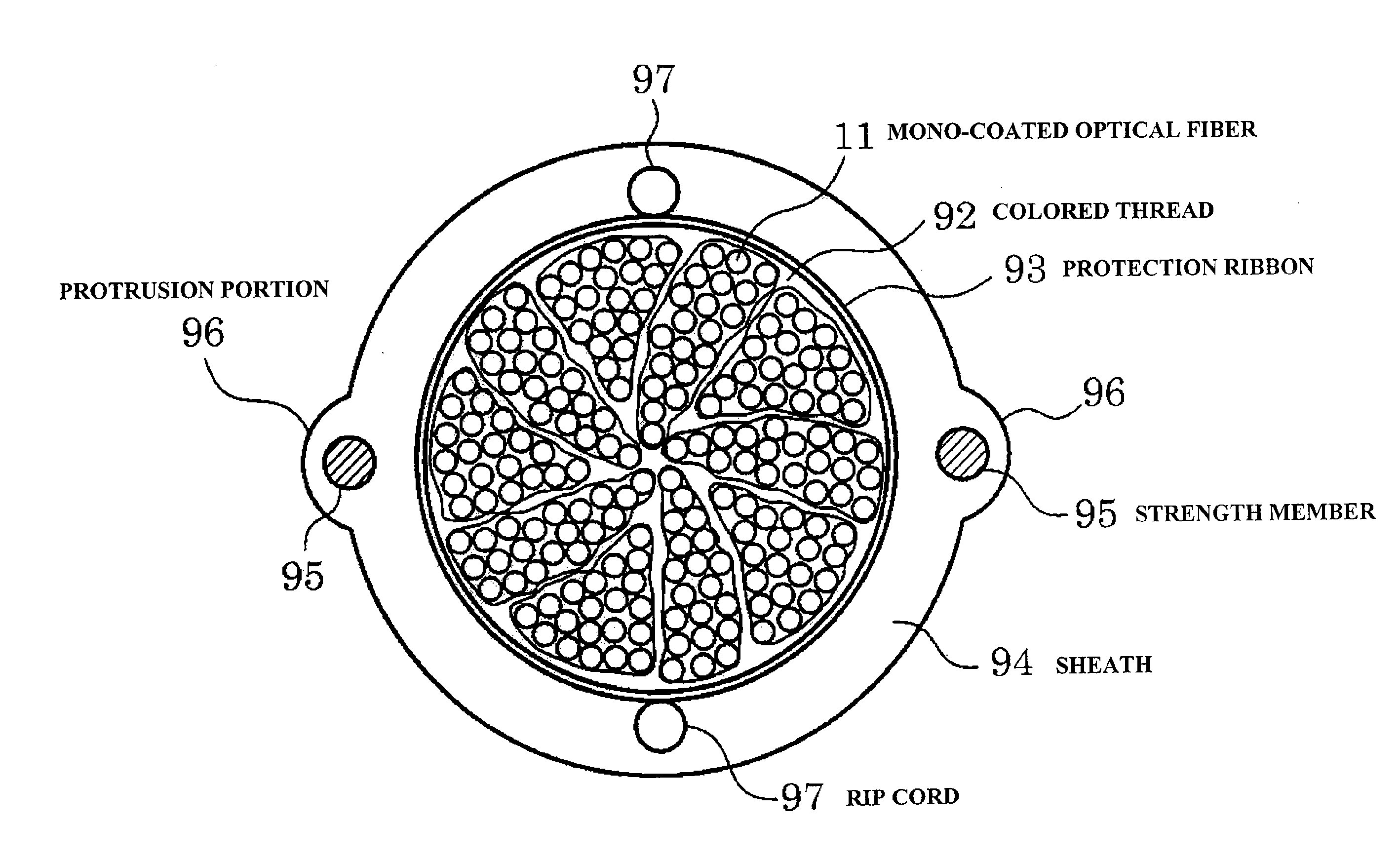
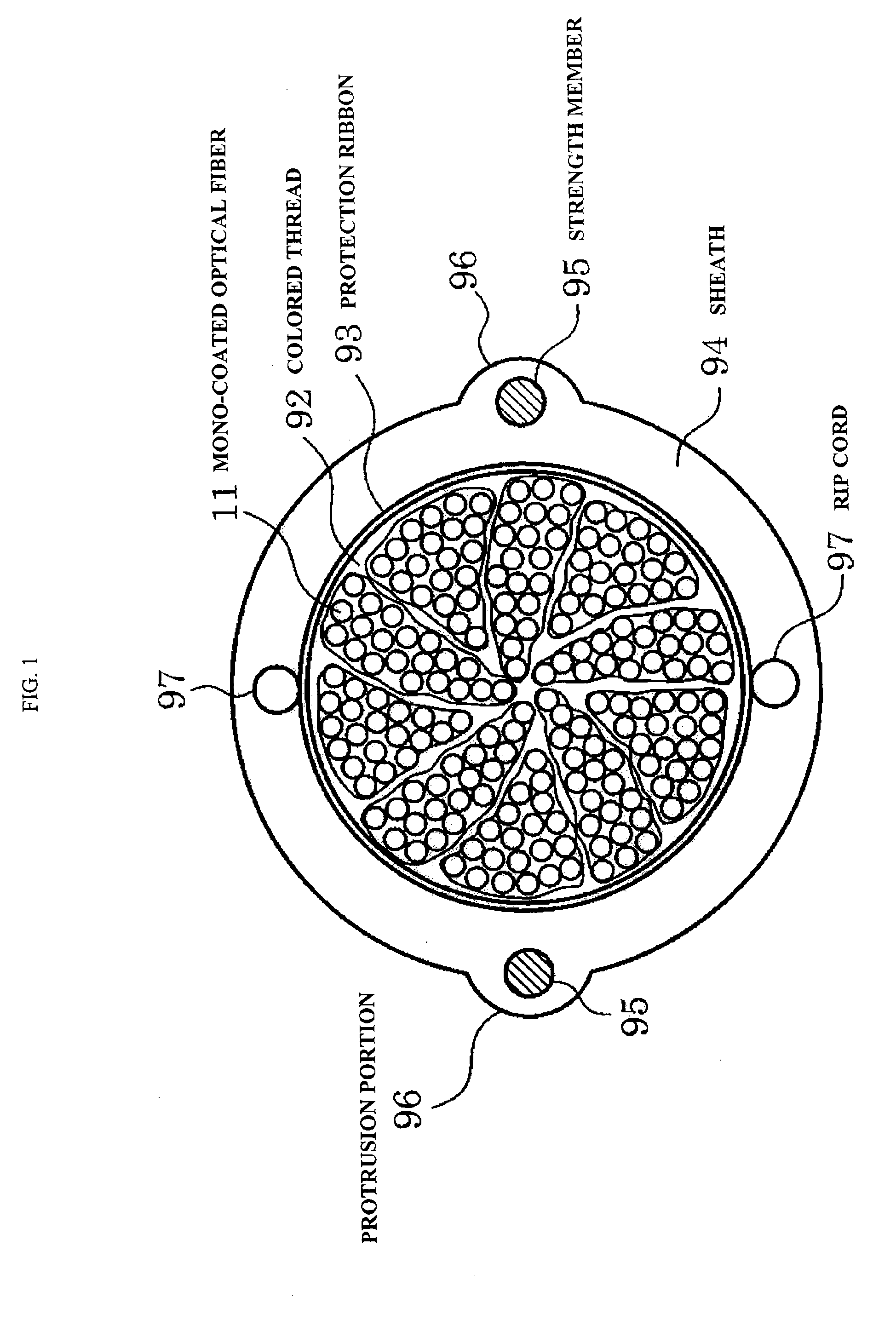
[0061]FIG. 1 is a cross-sectional view showing an optical fiber cable according to an embodiment of the present invention. In FIG. 1, 11 denotes a mono-coated optical fiber, 92 denotes a colored thread, 93 denotes a protection ribbon, 94 denotes a sheath, 95 denotes a strength member, 96 denotes a protrusion portion, and 97 denotes a rip cord.

[0062]As shown in FIG. 1, a unit that is configured by winding a colored thread 92 around the outer circumference of an optical fiber bundle where plural mono-coated optical fibers 11 with the diameter of 0.25 mm, for example, 20 mono-coated optical fibers are straightly and densely collected is formed, a wrapping layer that is composed of plural thin protection ribbons 93 is provided on the outer circumference of the optical fiber bundle where the plural units, for example, 10 units are twisted in one direction and densely collected, a sheath 94 is applied to the outer circumference, and a 200-fiber multiple optical fiber cable with the very h...

second embodiment

[0109]An embodiment of the present invention will be described in detail with reference to the accompanying drawings. FIG. 8(a) is a cross-sectional view showing an example of an optical fiber ribbon according to the first embodiment of the invention. FIG. 8(b) is a cross-sectional view showing another example of the optical fiber ribbon according to the first embodiment of the invention. In FIGS. 8(a), 11, 12, 13, and 14 denote mono-coated optical fibers and 15, 16, and 17 denote connecting portions.

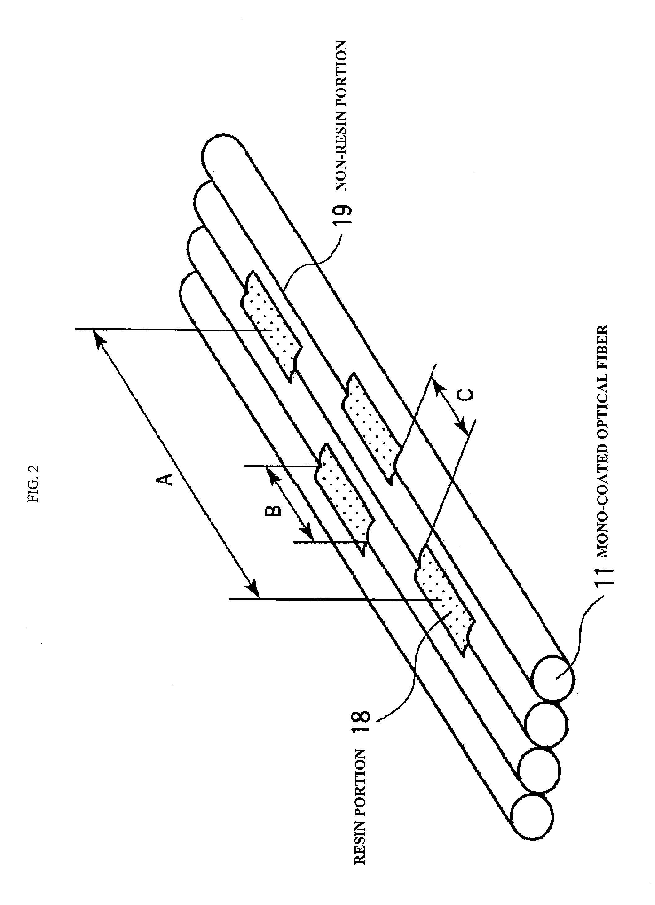
[0110]As shown in FIG. 8(a), plural (n) mono-coated optical fibers, for example, 4-fiber mono-coated optical fibers 11, 12, 13, and 14 with the outer diameter d (μm) are arranged. The mono-coated optical fibers 11, 12, 13, and 14 are disposed apart from each other, such that they do not contact each other, and the adjacent mono-coated optical fibers 11, 12, 13, and 14 are continuously connected in a longitudinal direction, by (n−1), that is, three connecting portions 15, 16, and 17.

[011...

third embodiment

[0149]The optical fiber cable that is described in FIG. 1 or 13 further includes a lateral pressure protection layer composed of a metallic tube 99 at the outer circumference of the sheath 94. The metallic tube 99 can be configured as a corrugated tube where corrugating working is performed. FIG. 15 shows the case where the optical fiber cable described in FIG. 1 includes the metallic tube 99. FIG. 16 shows the case where the optical fiber cable described in FIG. 13 includes the metallic tube 99. In the optical fiber cable shown in FIG. 15 or 16, since the metallic tube 99 becomes a buckler with respect to the cable lateral pressure, the metallic tube 99 can be directly buried in the ground without being installed in a conduit.


PUM


Abstract

Amono-coated optical fiber that has a bending loss characteristic in which an optical loss increase at a bending radius 13 mm is 0.2 dB / 10 turn or less, an optical fiber ribbon that includes two-dimensionally disposed resin portions for bonding the adjacent 2-fiber mono-coated optical fibers in plural places, the resin portions being disposed apart from each other in the longitudinal direction of the optical fiber ribbon and an optical fiber cable that includes a cable core portion that stores twisting of plural units where the mono-coated optical fibers constituting the optical fiber ribbon are collected.

Description

TECHNICAL FIELD[0001]The present invention relates to an optical fiber ribbon and an optical fiber cable that are components of an information wiring line using an optical fiber indoors and outdoors.BACKGROUND ART[0002]At the present time, due to an increase in broadband services, the number of FTTH subscribers using an optical fiber rapidly increases. As a result, in maintenance of infrastructure such as a conduit line that lays an optical fiber cable, a space to additionally lay the optical fiber cable is insufficient. For this reason, if the optical fiber cable is constructed to have the minute diameter and the high density, this becomes very effective in making effective use of infrastructure equipment.[0003]As the optical fiber cable that is constructed to have the small diameter and the high density, for example, Patent Document 1 suggests a multiple optical fiber cable that has the very small diameter and the high density using a structure in which sheathing is applied on the...

Claims


Application Information

Patent Timeline
Patent Type & Authority Patents(United States)
IPC IPC(8): G02B6/44
CPCG02B6/4403G02B6/4433G02B6/441
Inventor TOGE, KUNIHIROYAMADA, YUSUKEHOGARI, KAZUO
Owner NIPPON TELEGRAPH & TELEPHONE CORP
Why Eureka
Try Eureka